Primary Switch Mode Rectifier
PSS30
User manual
Page 8 (28)
Eltek Valere Industrial ©2008 UM_PSS30_E_R00
3. Start up procedure
Before connecting to the input voltage, it should be checked that the voltage information on the type
plate corresponds to the available voltage and also that the polarity corresponds to the connection
plan of the plug. The mains connection is done via a plug at the front side. The protective conductor
should be generally connected (protection class 1, leakage current ≤ 3.5mA).
Important:
If one pole is grounded at the output side, the module has to be connected with an additional non-fused
earthed conductor wire on the earth screw (left side on front panel). In this case the PE wire should not
be connected to the input connector to prevent earth circuit. This is very important for paralleled mod-
ules without decoupling diodes at the output side.
The DC output and signal contacts are to be connected with a SUB-MIN-D-connector, type 21WA4. For
modules with an output current >40A two heavy-duty contacts are paralleled. In this case it is impor-
tant that both contacts are symmetrically loaded. The current must be ≤40A per each contact. The
signalling contacts for monitoring, sense links and active current sharing mode are also included in the
output connector.
The rectifier has big capacitors at the output. If you connect a switched off module to a battery or
other modules which operates in parallel, a high capacitor charge current will occur. This current can
destroy the contacts on the output connector.
You can avoid this effect considering the following rules:
• Switch on the PSS module before connecting the output plug
• Disconnect the DC bus by switch or fuse
• Charge the capacitors with resistor (approx. 1 Ohm/V)
• Use decoupling diodes at the output side
After switching off, the capacitors are still fully charged. The discharge time is approx. 4s for the input
and approx. 15s for the output side.
The rectifier is forced-cooled with fan. The ambient temperature has to be lower than 45 °C. If more
than one subrack mounting level is used in one cabinet there must be a difference between two
mounting levels of 3U (approx. 130mm) for an unobstructed airflow. The temperature within the cabi-
net should not be higher than 40 °C.
If there is a higher temperature the life time of the modules will be decreased.
The internal losses per module are approx. 260 up to 290W (depending on the type).
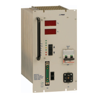
4. Operation
All operation elements are fitted on the front panel of the module. The function of each individual
operation element is described on the following pages.
See also section 7. “Operation elements and connectors”.
 Loading...