Primary Switch Mode Rectifier
PSS30
User manual
Page 12 (28)
Eltek Valere Industrial ©2008 UM_PSS30_E_R00
5.3.2 Operation monitoring
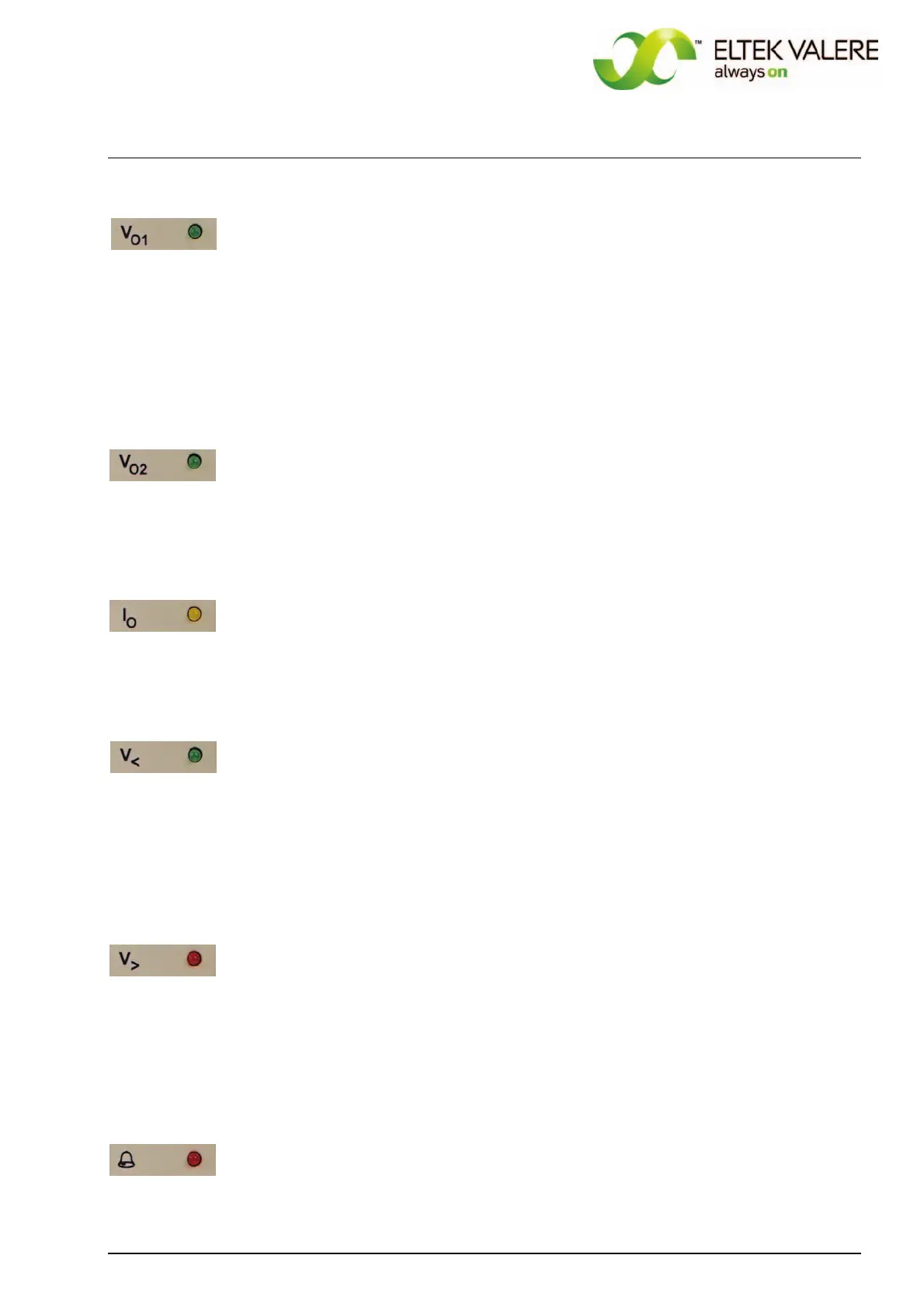
Functional monitoring; signalling with LED "V
O1", criterion: output voltage ≥ 97 % of adjusted output
voltage without constant current regulation; ≥ 85 % of adjusted output voltage with constant current
regulation. The signalling threshold of this monitoring automatically follows the adjusted nominal out-
put voltage.
This signal is included in the collective failure signal of the rectifier. Additional there is an optocoupler
signal (Vo O.K.) available.
At operation with internal decoupling diodes the voltage is measured ahead of the diodes.
5.3.3 Monitoring „Boost charge“
If „boost charge“ is activated (see section 6.5), LED V02 is ON, LED V01 is OFF.
5.3.4 Monitoring „Constant current operation“
Constant current operation (output current limiting active) is signalled with a yellow LED I
0.
5.3.5 Output voltage low
Output voltage low monitoring; signalling with LED "V<", criterion: Output voltage is higher than ad-
justed level V<; this signal is included in the collective failure signal of the rectifier.
This signal has its own relay contact on the signalling connector. If the voltage value is O.K., pin 13 and
pin 17 of X2 are closed.
5.3.6 Output voltage high
Output voltage high monitoring; signalling with LED "V>", criterion: output voltage higher than adjusted
level V>;
This signal is included in the collective failure signal of the rectifier. If there is an error, the LED is ON
and the rectifier internally switches off. You have to reset the unit by ON/OFF switch.
5.3.7 Protection against overheating/collective failure
A collective failure is signalled with the LED “Bell symbol”. Furthermore overheating is signalled;
criterion: Temperature of the heat sink > 90°C (the unit switches OFF). This signal is included in the
collective failure signal. You have to reset the unit by ON/OFF switch.
 Loading...