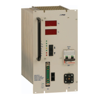
Primary Switch Mode Rectifier
PSS30
User manual
Page 21 (28)
Eltek Valere Industrial ©2008 UM_PSS30_E_R00
1)
Tri-state-input, pin 8 at -VO = discharge test mode; pin 8 at +VO = boost charge mode
NOTE: For the connection to +Vo an additional series resistor (150kOhm for the 216V version) is to be
used.
2)
Connection of a temperature sensor with 2-pole wire to pin 9 (+) and pin 7 (-)
NOTE: If several modules are paralleled, pin 9 of each individual unit and pin 7 of each individual unit has
to be connected.
3)
At active current sharing mode of paralleled units pin 10 of each individual module has to be con-
nected.
4)
External switch on/off with optocoupler: internal series resistor 2,7kOhm, I
min
< = 5mA, I
max
= 10mA
(see section 6.3).
NOTE: The input is potential free with save electrical decoupling to primary side and with 500VDC to
secondary side.
5)
The relay outputs are potential free with save electrical decoupling to primary side and with 500VDC
to secondary side.
6)
At active current sharing mode of paralleled units pin 4 (X2) of each individual module has to be
connected.
ATTENTION! You can use version
6
) or version
3
) for the wiring of the active current sharing mode, but
not both in combination
!
ATTENTION! If decoupling diodes are output-side integrated in minus
, the use of sense links are not
allowed.
8. Maintenance
In general, the PSS rectifier is maintenance-free.
A yearly inspection with following checks is recommended:
• Mechanical inspection
• Removal of dust and dirt, especially on radiator surfaces
• Check for internal dust or humidity
Attention! Dust combined with moisture or water may influence or destroy the internal electronic cir-
cuits.
Dust inside the unit can be blown out with dry compressed air.
The intervals between this checks depends on ambient conditions of the installed module.
 Loading...