Primary Switch Mode Rectifier
PSS30
User manual
Page 20 (28)
Eltek Valere Industrial ©2008 UM_PSS30_E_R00
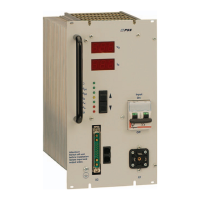
Signals (connector X4 = 15 x COMBICON 1,5mm
2
):
Pin assignment of X4 for PSS30/216V with signalling relay (without CAN-Bus)
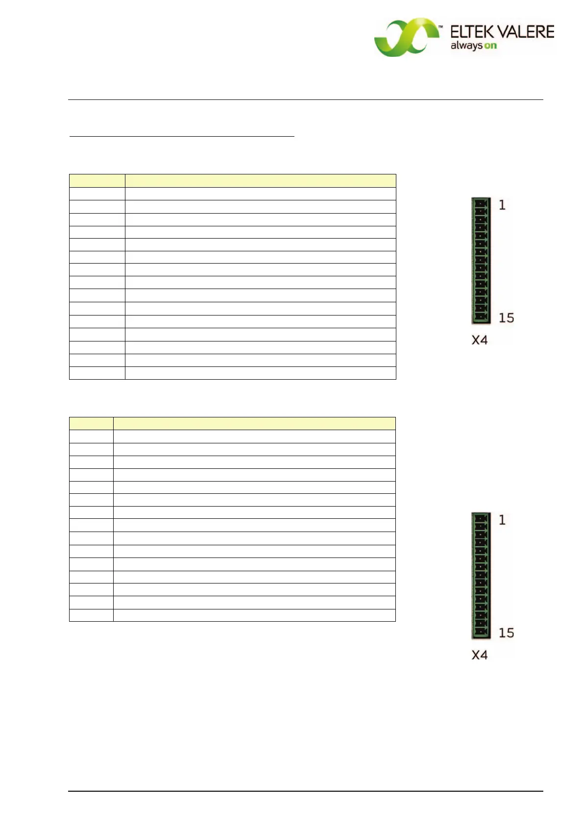
Pin assignment of X4 for
PSS30/216V with CAN-Bus
(without signalling relay)
REMARK: The legend of the items
1)
…
6)
follows on the next page.
X4, pin
Function
1
(+) external switch on/off
4
)
2
(-) external switch on/off
3 optocoupler emitter
4 optocoupler collector "Mains O.K."
5 optocoupler collector "VO O.K."
6 optocoupler collector "IO"
7 BUS ground
8
signal input discharge test mode / boost charge mode
1
)
9
temperature sensor (+)
2
)
10
control wire for current sharing mode
3
)
11
relay contact V< , NO
5
)
12
relay contact collective failure , NO
5
)
13 relay contact collective failure , COM
14
relay contact collective failure , NC
5
)
15 relay contact V< , COM
X4, pin
Function
1
(+) external switch on/off
4
)
2
(-) external switch on/off
3 optocoupler emitter
4 optocoupler collector "Mains O.K."
5 optocoupler collector "VO O.K."
6 optocoupler collector "IO"
7 BUS – GND
8
signal input discharge test mode / boost charge mode
1
)
9
temperature sensor (+)
2
)
10
control wire for current sharing mode
3
)
11
CVCC +
12 CAN-H
13 CAN-L
14
CVSS -
15 Not connected
 Loading...