Primary Switch Mode Rectifier
PSS30
User manual
Page 19 (28)
Eltek Valere Industrial ©2008 UM_PSS30_E_R00
1)
Tri-state-input, pin 2 at -VO = discharge test mode; pin 2 at +VO = boost charge mode
NOTE: For 60/108/216V units: For the connection to +V
O an additional series resistor is to be used
(60 V: 18kOhm; 108 V: 56kOhm; 216V: 150kOhm).
2)
Connection of temperature sensor with 2-pole wire to pin 7(+) and pin 10 (-)
NOTE: If several modules are paralleled, pin 7 of each individual unit and pin 10 of each individual unit
has to be connected.
3)
At active current sharing mode of paralleled units the pin 8 of each individual module has to be con-
nected.
4)
External switch on/off with optocoupler: internal series resistor 2,7kOhm, I
min
< = 5mA, I
max
= 10mA
(see section 6.3).
NOTE: The input is potential free with safe electrical decoupling to primary side and with 500VDC to
secondary side.
5)
The relay outputs are potential free with safe electrical decoupling to primary side and with 500VDC
to secondary side.
ATTENTION! If decoupling diodes are output-side integrated in minus, the use of sense links are not
allowed.
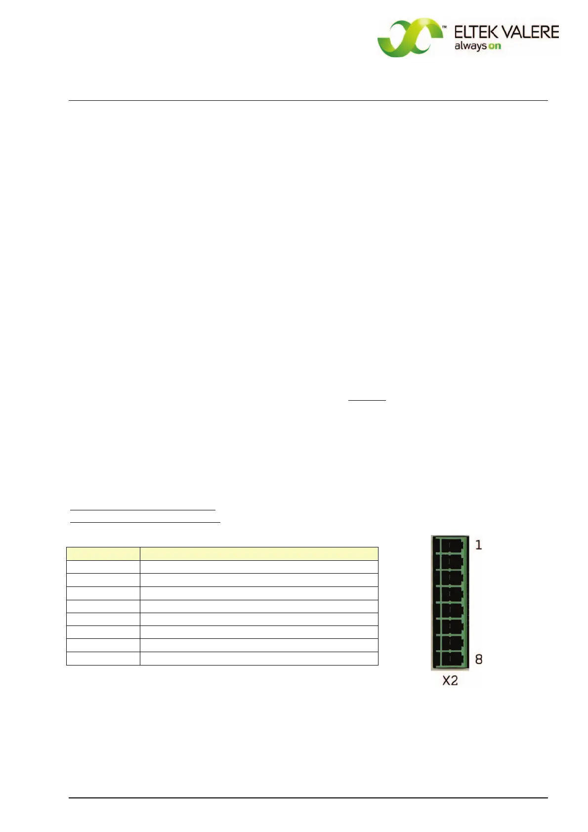
For the 216V version, the DC output and signal connectors are separated.
DC output (8xCOMBICON 4mm
2
)
for 216V version (connector X2):
X2, pin
Function
1
(+) - output
2
(+) - output
3
(+) - voltage sense link
4
control wire for active current sharing
6
)
5 BUS ground
6
(-) - voltage sense link
7
(-) - output
8
(-) - output
 Loading...