Primary Switch Mode Rectifier
PSS30
User manual
Page 18 (28)
Eltek Valere Industrial ©2008 UM_PSS30_E_R00
7.3 Electrical connectors
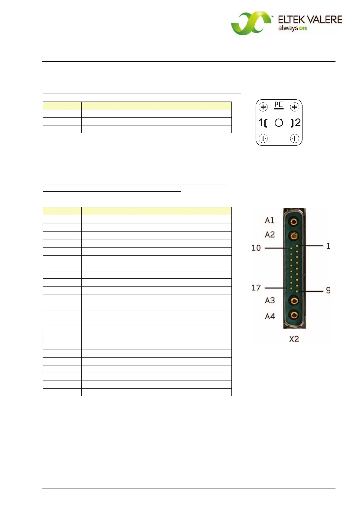
AC-mains input (GDM-connector) for all PSS30 versions (connector X1)
X1, pin
Function
1 L1 - Input
2 N - Input
PE PE
X1
DC output and signalling contacts (SUB-MIN-D-connector 21WA4),
for 24, 48, 60 and 108V versions (connector X2):
X2, pin
Function
A1
(+) - output
A2
(+) - output (additional for Io ≥ 40A)
A3
(-) - output (additional for Io ≥ 40A)
A4
(-) - output
1
(+) - output voltage sense link
2 signal input discharge test mode / boost charge
mode
1
)
3 optocoupler emitter
4 optocoupler collector "Mains O.K."
5 optocoupler collector "Vo O.K."
6 optocoupler collector "Io"
7
temperature sensor (+)
2
)
8
control wire for active current sharing
3
)
9
(-) - output voltage sense link
10 analogue ground (for temperature sensor (-), active
current sharing)
11
(+) external switch on/off
4
)
12
(-) external switch on/off
13
relay contact V< , N/O
5
)
14 relay contact collective failure , N/O
15 relay contact collective failure , COM
16 relay contact collective failure , N/C
17 relay contact V< , COM
REMARK: The legend of the items
1)
…
5)
follows on the next page.
 Loading...