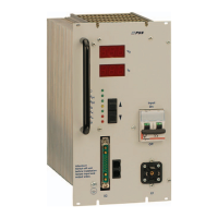
Primary Switch Mode Rectifier
PSS30
User manual
Page 15 (28)
Eltek Valere Industrial ©2008 UM_PSS30_E_R00
6.4 Discharge test
It is possible to test the capacity of a battery which operates in parallel with the rectifier.
To select the discharge test mode you have to connect –Vo to pin 2 of the output connector X2 (see
section 7.3).
The discharge test voltage can be adjusted by the user (parameter V
O3; see section 5.4).
If the discharge test mode is active, the LED V
O1 is ON; LED VO2 is OFF.
6.5 Boost charge mode
The rectifier module has a second charge line (boost charge line). To select this mode you have to
connect +Vo to pin 2 of the output connector X2 (see section 7.3). The boost charge mode is
signalized by LED V
O2. The voltage value can be adjusted by the user (see section 5.4).
NOTE: For 60/108/216V units: For the connection to +V
O an additional series resistor is to be used
(60 V: 18kOhm; 108 V: 56kOhm; 216V: 150kOhm).

 Loading...