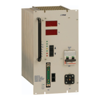
Primary Switch Mode Rectifier
PSS30
User manual
Page 14 (28)
Eltek Valere Industrial ©2008 UM_PSS30_E_R00
Adjustable parameters in the adjustment mode:
Displayed short term
of the parameters
Parameter meaning
VO1 trickle charge voltage
VO2 boost charge voltage (see section 6.5)
VO3 voltage at discharge test (see section 6.4)
Io output current
V< output voltage low threshold (see section 5.3.5)
V> output voltage high threshold (see section 5.3.6)
t temperature coefficient for temperature compensation of the charge
voltage (see section 6.2)
Adr change CAN-Bus address
The threshold values for mains/step-up-converter and over heating are not changeable.
The threshold values of DC voltage low (V<) and DC voltage high (V>) can be individually set within a
limited adjustment range.
For more information regarding the adjustment ranges and factory preset values see section
10. “Technical data”.
6. External Functions
6.1 Output voltage sensor leads
Voltage losses at wires or diodes are to be compensated with sense links for the output voltage.
The maximum regulation difference is approx. 4 % of the nominal voltage.
Cable break at sense links, confusing of poles or short circuit can not damage the rectifier. At cable
break of the sense link, a voltage increase of max. 4% is possible.
6.2 Temperature compensation of the charging voltage
For the use of closed batteries we recommend temperature-controlled compensation of the charge
voltage.
Connect an external active temperature sensor (option) to the signalling connector. The standard set
temperature coefficient is -4mV/K per cell (for a temperature range of 0-50 °C). The basic temperature
is 20°C. The coefficient can be adjusted between 0 to -6mV/K per cell (see section 5.4).
Connect the sensor with a 2-pole wire (0,25mm
2
). It can be directly mounted on top of the battery or on
battery poles. At great distances (approx. 2m) we recommend the use of a shielded wire with connec-
tion of the shield to rectifiers ground.
6.3 External switch ON/OFF function
The rectifier can be externally switched on/off with applying an external DC voltage over an external
switch to the respective pins according to section 7.3. The output of the PSS rectifier switches OFF, if
the external voltage is applied. In this case, the switch-off does not result in a collective failure signal!
The input is potential free due to the use of an optocoupler and meets the supposition for safe electri-
cal decoupling to mains and output side. The signalling voltage is 10-24V, the internal resistance is
2,7kOhm. The input is protected against reversed polarity. At higher supply voltages the current in the
control circuit has to be limited to approx. 5-7mA with a series resistor (e. g. 6,8kOhm at 48/60V
DC).
 Loading...