12 BA-en-3031-2004_KNH35
3.2 Ground connection
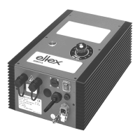
A permanent grounding connection must be made and checked via the
ground terminal (3, Fig. 1 - Fig. 2) and routed with the shortest possible
distance to the machine frame. The ground cable should have a minimum
cross section of 1.5 mm
2
. If the length of the cable is > 0.5 m, the cross-
section must be at least 2.5 mm
2
.
3.3 Installation of the high voltage cables
• A minimum bending radius of 10 times the external diameter must be
maintained when routing the high voltage cable.
• The high voltage cables must not be attached with metal clips.
• Do not route the cable over sharp edges (bending radius <5 mm).
• Keep a minimum spacing of 50 mm between low voltage and high vol-
tage cables; if this cannot be done, shield the low voltage cable.
• If the high voltage cables are led through bores in conductive, grounded
materials, the minimum bore diameter D is calculated as follows from
the wall thickness of the material:
Bore hole diameter D (mm) = 60 mm² / wall thickness (mm)
E.g. wall thickness 2 mm: D = 60 mm² / 2 mm = 30 mm
Allow the biggest possible radius for the edges of the bore hole. Use an
insulating grommet to centre the cable.
• If ungrounded and conductive objects are placed near (2m) the high
voltage cable, influenced charges and sparking must be expected.
Proper ground connection is therefore important.
• In applications using movable bars (e.g. film draw strips), route the high
voltage cables such that there is no cable movement near the connec-
tion point to the generator.