www.emachines.com
41
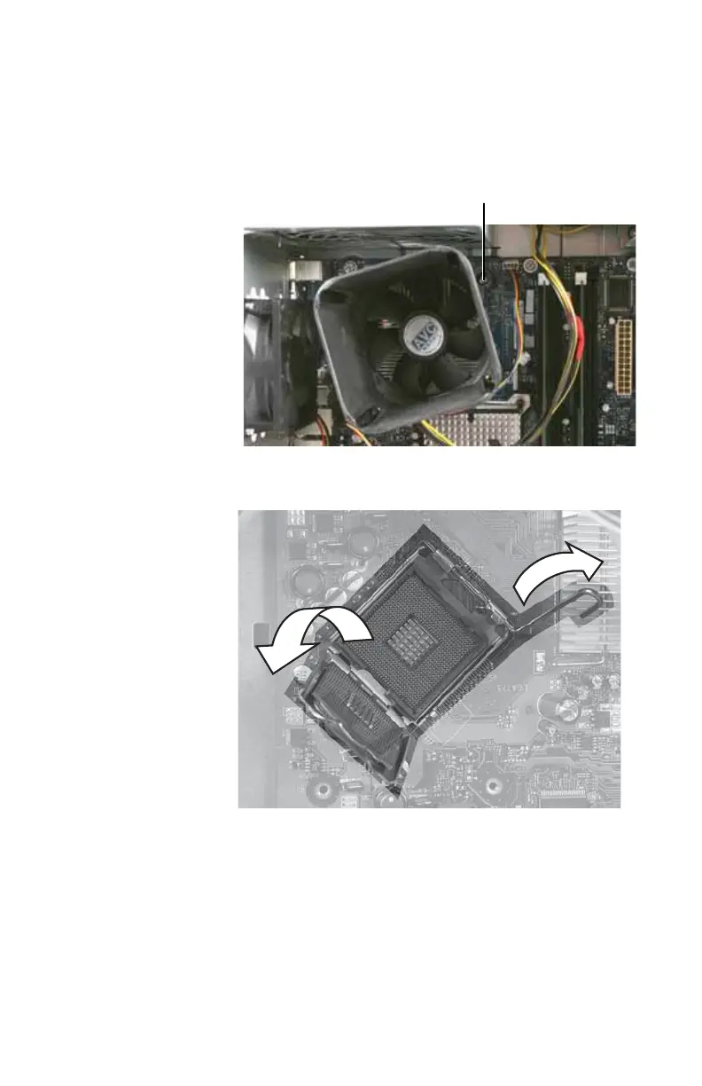
4 Loosen the four captive screws (these screws cannot be
removed) that secure the heat sink and fan assembly to
the system board, then remove the assembly and place
it on a stable surface with the flat surface of the heat sink
(the side with the thermal grease) up.
5 Push the processor release lever down, lift it completely
up, then lift the processor retention bracket.
6 Remove the processor from the system board.
7 Install the new processor onto the system board. Make
sure that Pin 1 on the processor (indicated by the
silk-screened arrow on the corner of the processor)
aligns with Pin 1 on the processor socket (indicated by
the absence of a pin hole in the processor socket), then
return the retention bracket and lever to their locked
position.
Screws (only one shown)
8512635.book Page 41 Friday, July 27, 2007 11:21 AM