CHAPTER 4. OPERATION 30
0 2
4
6
8 10 12
14
16
18 20 22
0
5
10
15
Time [ms]
Amplitude [V]
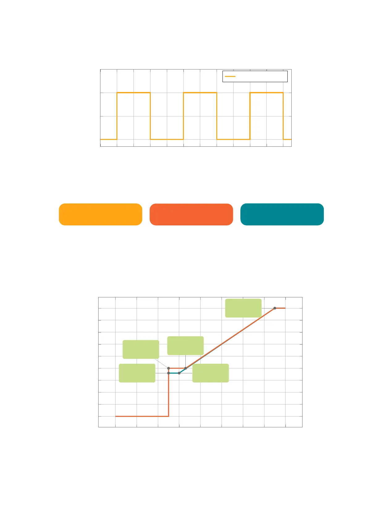
Signal control shape
Duty-cycle: 50%
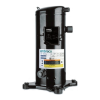
The compressor will follow frequency signal sent to the inverter according to the
relation described on the following table and illustrated on the graph below.
Input Frequency
Signal [Hz]
VNE compres-
sor speed [RPM]
VEG and FMF com-
pressor speed [RPM]
0 to 50 0 0
50 to 60 2000 1800
60 to 66 2000 30 x Hz
66 to 150 30 x Hz 30 x Hz
>150 4500 4500
0 20
40
60
80 100 120
140
160
0
500
1,000
1,500
2,000
2,500
3,000
3,500
4,000
4,500
66Hz
2,000RPM
50Hz
2,000RPM
50Hz
1,800RPM
150Hz
4,500RPM
60Hz
1,800RPM
Frequency [Hz]
Speed [RPM]
Compressor speed versus Frequency signal
The Figure 4.1 shows the electrical connections to perform frequency conmmu-
nication between an electronic thermostat and Fullmotion CF10C Inverter Control
connector. For Frequency Control Mode, the input resistance is 1.2 kΩ.