110 EMC VNX8000 Hardware Information Guide
Disk-array enclosures
The 10 fans within the DAE are arranged in two separate rows of 5 fans each (front and
mid-section). Each row and instance is labeled with a fan icon and corresponding
number; front = 0, mid-section = 5. Each fan is numbered sequentially 0-9, left to right,
with 0-4 being in the front row. For information about replacing a fan module, go to
Replacing a fan module in a 120-disk enclosure
procedure available online at
https://mydocs.emc.com/VNX/ and go to VNX Tasks,
then select Replace VNX hardware.
Next, follow the steps in the wizard.
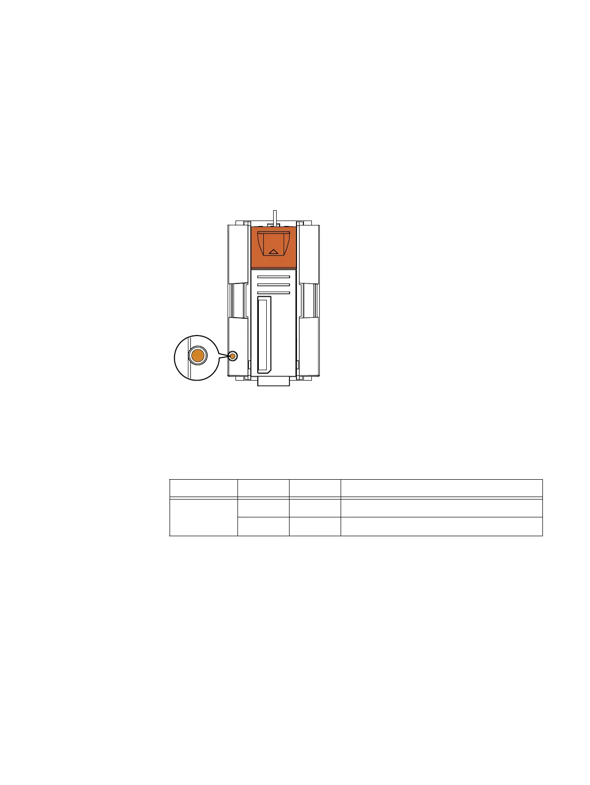
Figure 92 shows the location of the status (fan fault) LED on the 3U, 120 (2.5-inch) DAE
fan module.
Figure 92 Example of a 3U, 120 DAE fan module showing the fan fault LED (amber)
Table 46 describes the 3U, 120 DAE fan fault LED.
CL5364
Table 46 Fan module fan fault LED
LED Color State Description
Fan fault Amber On Fault detected, one or more fans faulted
— Off No fault detected, fans operating normally

 Loading...


