Disk-array enclosures
EMC VNX8000 Hardware Information Guide 113
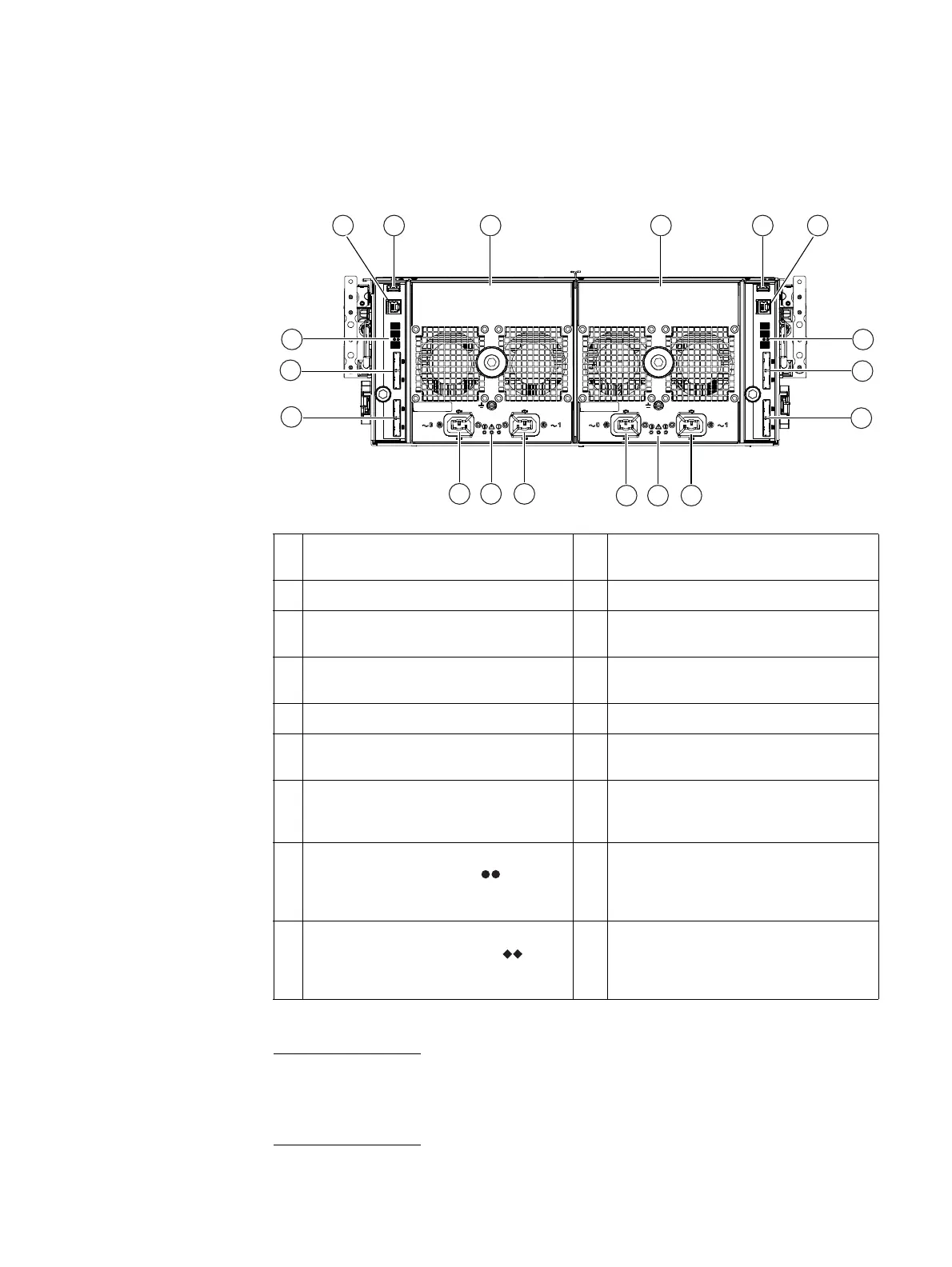
Rear view
On the rear, viewing from left to right, a 4U, 60 (2.5- or 3.5-inch) DAE includes two 6 Gb/s
SAS ICMs (A and B) and two power supply modules (A and B) as shown in Figure 95.
Figure 95 Example of a 4U, 60 DAE with two ICMs and two power supply/cooing modules (rear view)
Note: Between the power supplies and the ICMs on the rear of the 4U, 60 DAE is a
separator bar that indicates the location of the both power supplies and ICMs. Facing rear,
on the right side of the 4U, 60 DAE, is power supply A and ICM A. On the left side of the
40U, 60 DAE is power supply B and ICM B.
1 ICM B management (RJ-12) connector (not
used)
10 4U, 60 DAE A AC power supply power in
(recessed plug), labeled 1
2 ICM B USB connector 11 4U, 60 DAE A power and fault LEDs
3 4U, 60 DAE B AC power supply) 12 4U, 60 DAE A AC power supply power in
(recessed plug), labeled 0
4 4U, 60 DAE A AC power supply power in
(recessed plug)
13 4U, 60 DAE B AC power supply power in
(recessed plug), labeled 1
5 ICM A USB connector 14 4U, 60 DAE B power and fault LEDs
6 ICM A management (RJ-12) connector (not
used)
15 4U, 60 DAE B AC power supply power in
(recessed plug), labeled 0
7 4U, 60 DAE B bus ID and enclosure ID 16 ICM B SAS connector (output); the top port
is labeled 0 and the bottom port is labeled
1.
8 ICM A SAS connector (input); labeled with
a double circle (dot) symbol
. The top
port is labeled 0 and the bottom port is
labeled 1.
17 ICM B SAS connector (input); the top port
is labeled 0 and the bottom port is labeled
1.
9 ICM A SAS connector (output); labeled
with a double diamond symbol
. The
top port is labeled 0 and the bottom port
is labeled 1
18 4U, 60 DAE B bus ID and enclosure ID
2 43 51
6
7
8
10
VNX-000627
1112
131415
18
16
9
17

 Loading...


