EasyManuals Logo

EMC VNX Series Hardware Information Guide

EMC VNX Series
170 pages
To Next Page IconTo Next Page
To Previous Page IconTo Previous Page
Page #119 background imageLoading...
Page #119 background image
Disk-array enclosures
EMC VNX8000 Hardware Information Guide 119
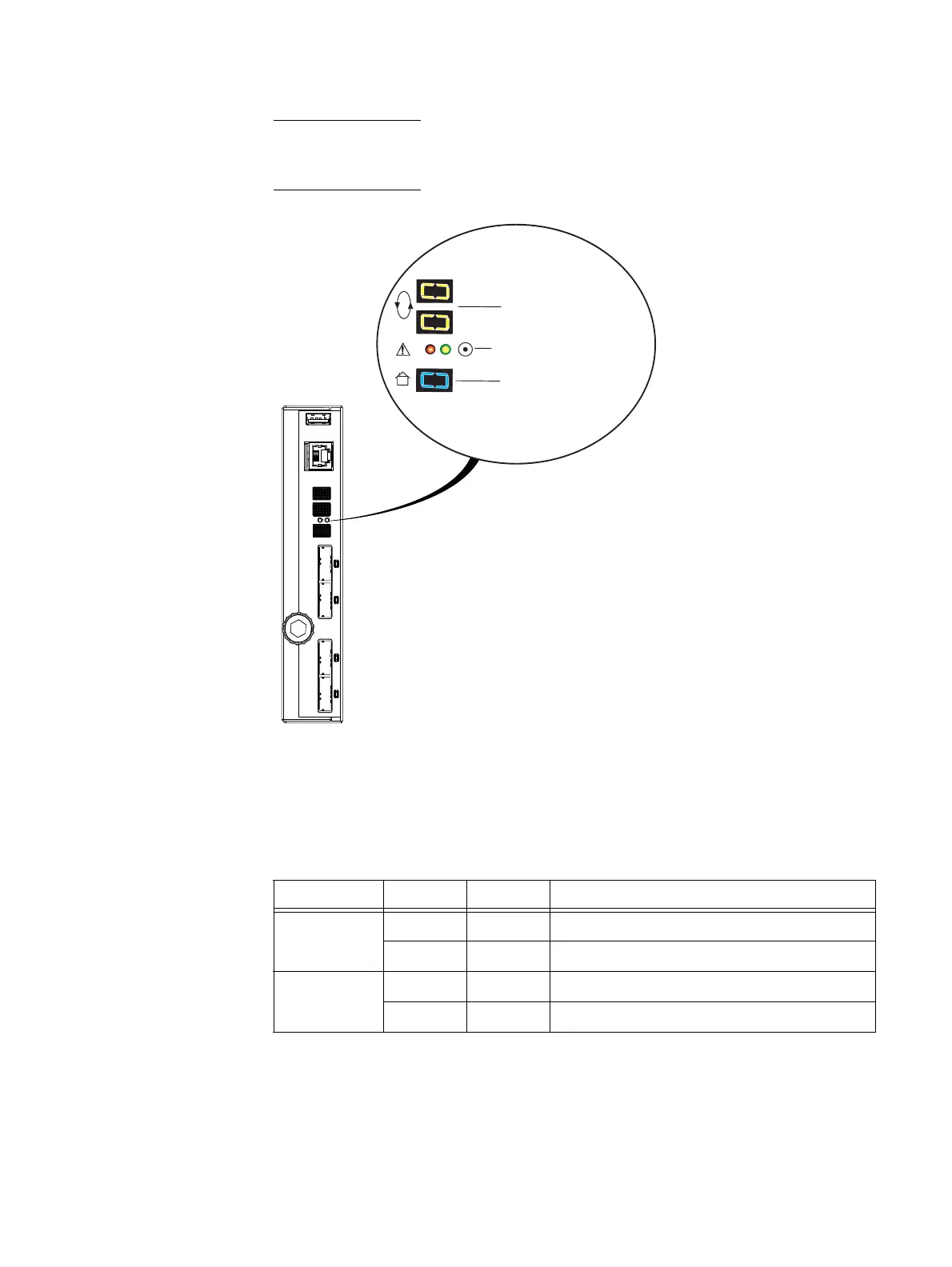
Note: Figure 101shows the bus ID indicator, enclosure ID indicator, and the ICM power on
and fault LEDs when viewed from the horizontal side of the ICM. Normally, you would have
to turn your head to view these indicators.
Figure 101 Example of an ICM enclosure ID indicator, bus ID indicator, and the ICM power and fault
LEDs
Table 51 describes the ICM power and fault LEDs.
#
Bus (loop) ID
DAE ICM status LEDs,
fault (left) and power (right)
Enclosure ID
VNX-000651
Table 51 ICM (power and fault) status LEDs
Led Color State Description
Power on Green On Power on
—OffPower off
Power fault Amber On Fault
Off No fault or power off

Other manuals for EMC VNX Series

Questions and Answers:

Question and Answer IconNeed help?

Do you have a question about the EMC VNX Series and is the answer not in the manual?

EMC VNX Series Specifications

General IconGeneral
Management InterfaceUnisphere
Drive SupportSAS, NL-SAS, Flash (SSD)
RAID LevelsRAID 0, 1, 3, 5, 6
Protocols SupportedFibre Channel, iSCSI, NFS, CIFS
Data ServicesDeduplication, Compression, Snapshots, Replication
ProcessorIntel Xeon
Operating SystemVNX Operating Environment (block), VNX File Operating Environment (file)

Related product manuals