System component description
EMC VNX8000 Hardware Information Guide 33
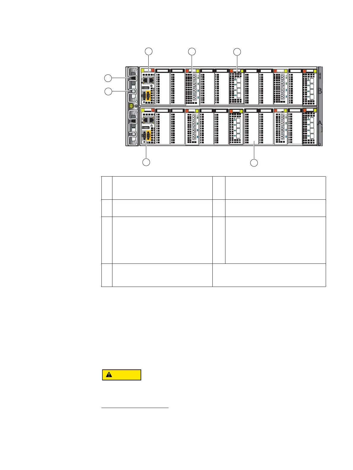
Figure 18 Example of SP components (rear view)
Storage processor AC power supply module
The storage processor (SP) power supply module is located on the left side of each SP
when viewed from the rear (see locations 1 and 2 in Figure 18). On the front (“Storage
processor (SP) AC power supply module” on page 18) of the power supply, each power
supply includes three status LEDs (AC, DC, and fault (labeled with an upside-down
exclamation point, !). A latch on the power supply locks it into place to ensure proper
connection.
Do not
remove the SP power supply module while the SP is plugged in. Power supply
module removal for more than a few minutes can cause the SP to shut down due to lack of
cooling.
1 SP B power supply (power in) recessed
connector (plug) from SPS B
5 SP B four-port 6-Gb/s SAS I/O module in
slot B5 (for a closer view, see “Four-port
6-Gb/s SAS I/O module” on page 61)
2 SP B power supply (power in) recessed
connector (plug) from SPS A
6 SP A I/O module filler panel
3 SP B (management module) showing two
RJ-45 (management and service laptop)
connectors labeled with a network
management symbol and a wrench
symbol, respectively (for a closer view, see
“Storage processor management module”
on page 34)
7 SP A (management module) showing two
RS-232/EIA (micro DB-9) connectors
(labeled with a battery symbol and a
wrench symbol, respectively) (for a closer
view, see “Storage processor management
module” on page 34)
4 SP B four-port 8-Gb/s FC I/O module in
slot A2 (for a closer view, see “Four-port
8-Gb/s FC I/O module” on page 48)
3
6
4
5
1
2
0123
0123
0123
0123
0
123
0
123
7
VNX-000800
0
123
0
123

 Loading...


