Disk-array enclosures
EMC VNX5400 Hardware Information Guide 105
Rules for disk drive population
As described in the previous paragraph, disks are arranged in six rows of twenty modules
each. The first (front) row is denoted as A, then the remaining rows are B, C, D, E, and F. In
each row, the disks are numbered with the first disk labeled with a letter and number
together, for example A0 or A19, and so on (for more information, refer to “Disk drive
layout” on page 104).
The required order of loading the disk drives into a 3U, 120 (2.5-inch) DAE is as follows
(Figure 83 on page 104):
1. Start at row (or bank) A, slot 0 or A0.
2. Fill up the row (or bank) A before inserting any disk drives into row B.
3. Continue this order until you fill all the rows with row F being the last row filled.
Note: If you partially fill a row, fill the remaining empty slots with filler panel modules.
Rows with no or zero (0) drives do not require filler panel modules.
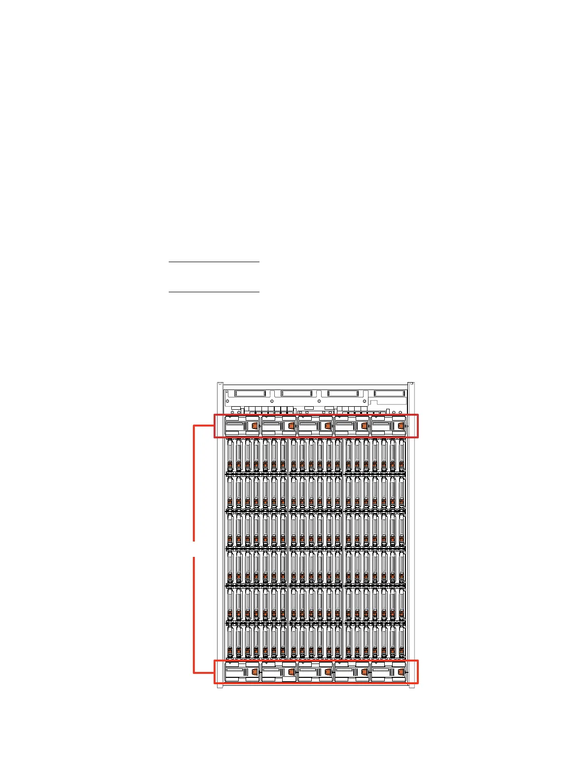
Fan module (cooling module)
As described previously in the section “Fan module (cooling module)” on page 91, each
3U, 120 (2.5-inch) DAE includes 10 fan modules (cooling modules). Figure 84 shows the
location of the fan modules in the 3U, 120 (2.5-inch) DAE.
Figure 84 Example of the 3U, 120 DAE fan module location
A
0
B
0
C
0
D
0
E
0
F
0
A
19
B
19
C
19
D
19
E
19
F
19
Fans X10

 Loading...


