108 EMC VNX5400 Hardware Information Guide
Disk-array enclosures
Front view
The 4U, 60 (2.5- or 3.5-inch) DAE has the following components:
◆ three fans, front
◆ up to 60 disks (five rows of twelve each), inside
◆ two link control cards (LCCs), inside
◆ two inter-connect modules (ICMs), rear
◆ two power supply modules, rear
Note: To see an example of the interior view of a 4U, 60 (2.5- or 3.5-inch) DAE, go to
Figure 96 on page 117. In this illustration, all of the main components are shown.
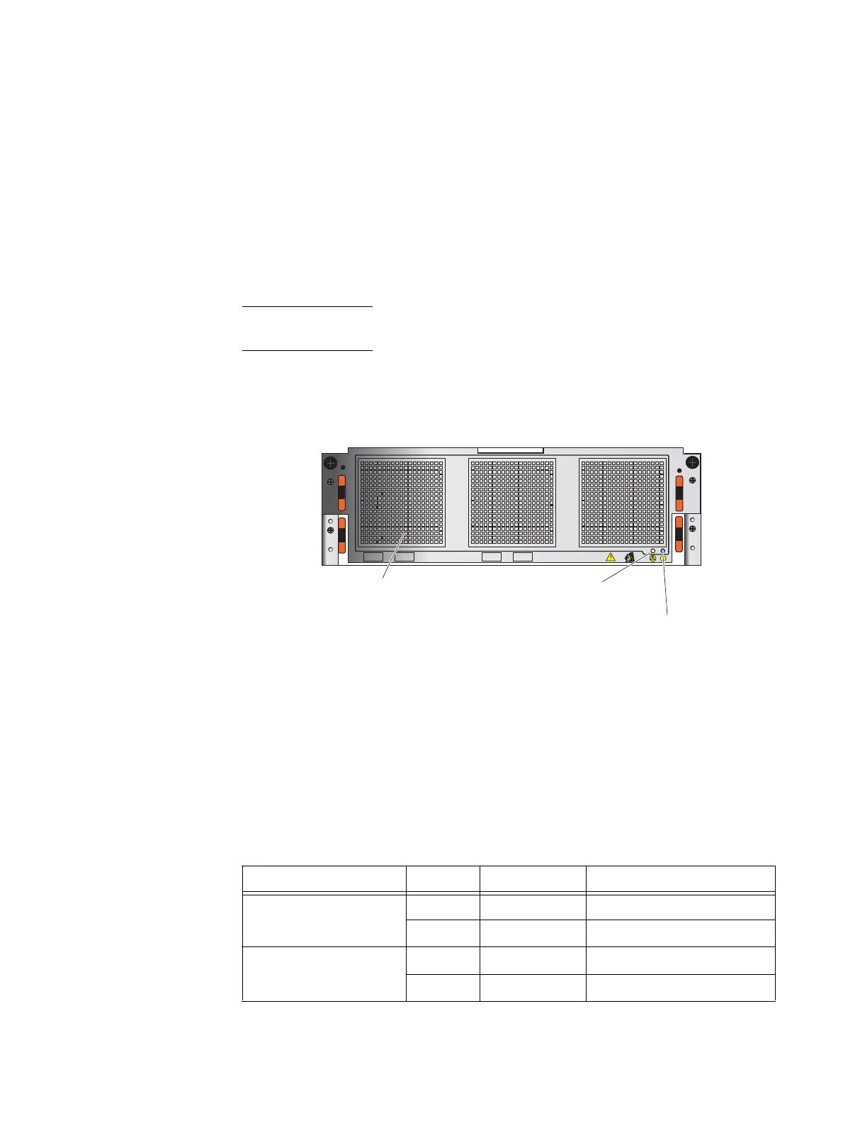
Figure 87 shows the front view of the 4U, 60 (2.5- or 3.5-inch) DAE having three fan
modules or cooling modules and two status LEDs (an enclosure fault led, an enclosure
power led).
Figure 87 Example of a 4U, 60 (2.5-or 3.5-inch) DAE (front view) showing the fan modules and the
DAE power fault LED (amber) and the DAE power on LED (blue)
4U, 60 (2.5- or 3.5-inch) DAE front status LEDs
On the front of the 4U, 60 (2.5- or 3.5-inch) DAE are two status LEDs:
◆ a DAE power fault LED (amber)
◆ a DAE power on LED (blue)
Table 48 describes the 4U, 60 (2.5- or 3.5-inch) DAE front status LEDs
1
2
1
2
Power on LED (blue)
Power fault LED (amber)
Cooling module (fan)
VNX-000528
Table 48 4U, 60 DAE status LEDs
LED Color State Description
DAE power on Blue On Powering and powered up
— Off Powered down
DAE power fault Amber On Fault detected
— Off No fault detected

 Loading...


