28 EMC VNX5400 Hardware Information Guide
System component description
B7 Rx 2+ D7 Tx 2+
B8 Rx 2- D8 Tx 2-
B9 Signal GND D9 Signal GND
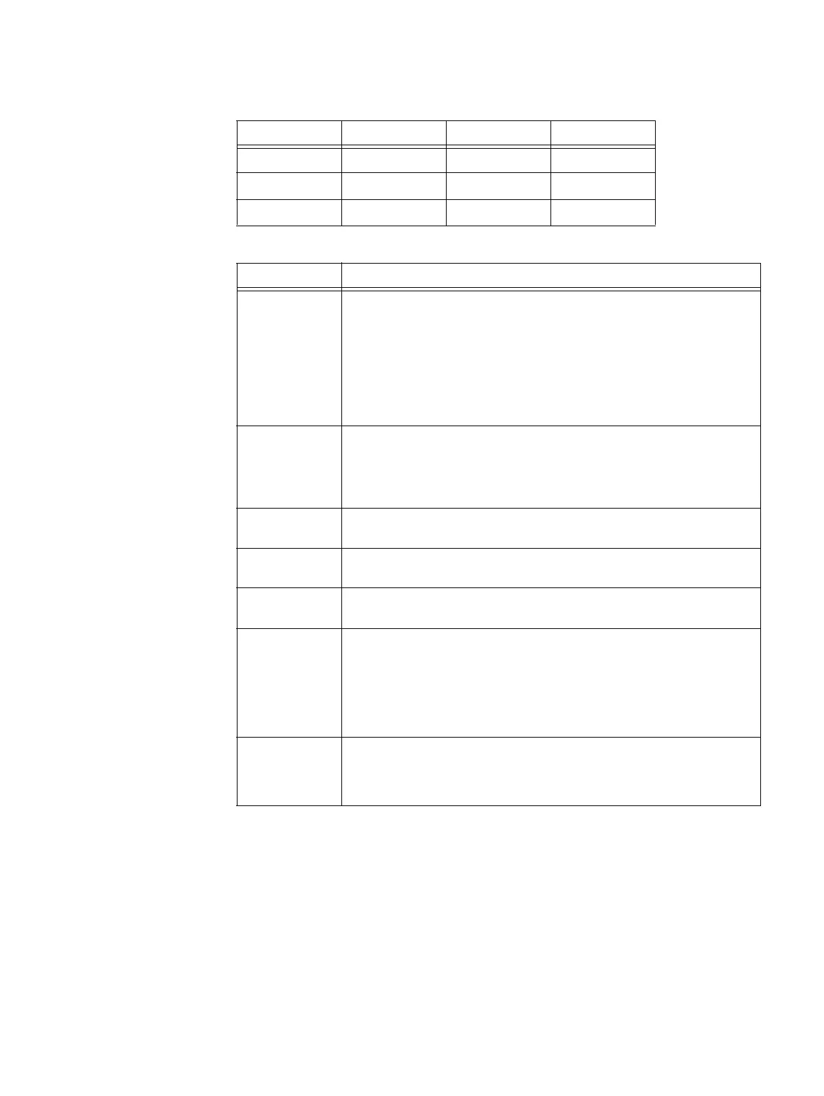
Table 10 Management Interface connection requirements
Signal Connection requirements
Intl Active Low Module Interrupt: The cable assembly asserts this pin to indicate
an interrupt bit has been set to one in the management interface memory
map. This pin is connected to Vman on the receptacle side of the management
interface. The source of the interrupt may be identified using the 2-wire serial
management interface. If a cable assembly does not support interrupts, then
all interrupt bits in the cable management interface memory map are set to
zero and the cable assembly negates this pin (e.g., all interrupt bits of a
passive cable assembly may be programmed to a clear state and the IntL pin
not connected on the cable plug side of the management interface).
ModPrsL Active Low Module Present: On the cable plug side of the management
interface, ModPrsL is connected directly to the signal ground pins specified in
Table 9 on page 27. ModPrsL is connected to Vman on the receptacle side of
the management interface to negate this signal when the plug is not fully
mated to the receptacle.
Reserved This pin is not connected on the receptacle side and cable plug side of the
management interface.
SCL Two-wire interface clock: The receptacle side of the management interface
connects this signal to Vman.
SDA Two-wire interface data: The receptacle side of the management interface
connects this signal to Vman.
Vact Active cable power: If the receptacle side of the management interface
supports active cable assemblies, then it provides all non-management
interface power to the cable assembly on the Vact pins. To support equal
loading, both Vact pins are connected together on the receptacle side of the
management interface. If the receptacle side of the management interface
does not support active cable assemblies, then the Vact pins is not
connected.
Vman Management interface power: The receptacle side of the management
interface provides power on the Vman pin to enable the management
interface circuitry of the cable. Power may be removed to reset the
management circuitry in the cable assembly.
Table 9 6-Gb/s mini-SAS HD port connector pinout (continued)
Pin Signal Pin Signal

 Loading...


