74 EMC VNX5400 Hardware Information Guide
Disk-array enclosures
Table 32 describes the 2U, 25 (2.5-inch) DAE and disk drive status LEDs.
Rear view
On the rear of a VNX5400 platform, the 2U, 25 (2.5-inch) DAE includes the following
components:
◆ Two link control cards (LCCs) A and B
◆ Two power supply/cooling modules (A and B)
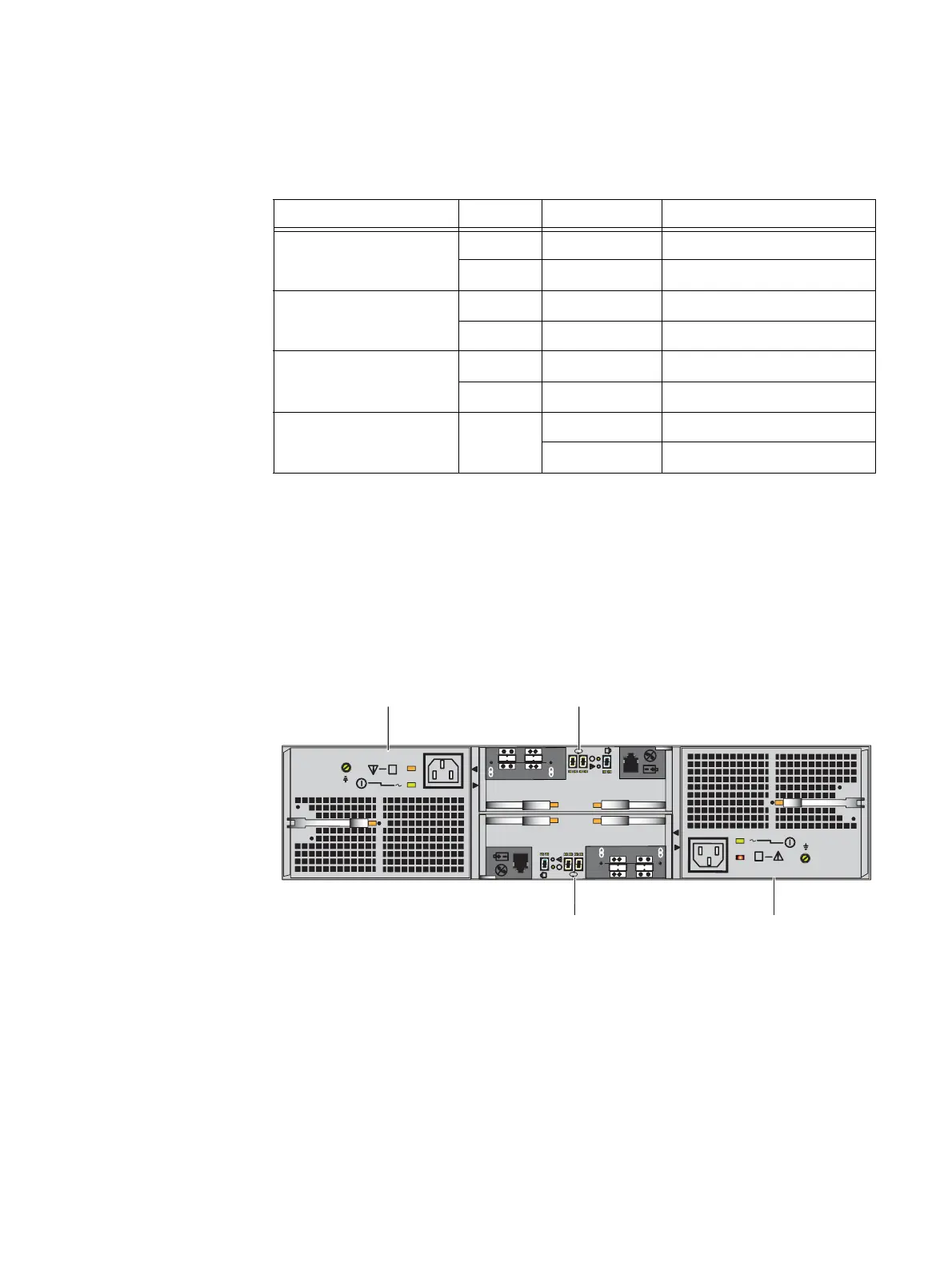
Figure 53 shows the location of these components.
Figure 53 Example of 2U, 25 (2.5-inch) disk drive DAE (rear view)
2U, 25 (2.5-inch) DAE LEDs and connectors
Figure 54 on page 75 shows the location of the 2U, 25 (2.5-inch) DAE LEDs, connectors,
and the latch handles:
◆ AC power supply (A and B) recessed power in (plug)
◆ AC power supply (A and B) LEDs (power and fault)
◆ AC power supply (A and B) latch handle
Table 32 2U, 25 (2.5-inch) DAE and disk drive status LEDs
LED Color State Description
DAE fault (see location 2) Blue On No fault has occurred
Amber On Fault has occurred
DAE power (see location 3) Blue On Powering and powered up
— Off Powered down
Disk drive fault
(see location 4)
Amber On Fault has occurred
— Off No fault has occurred
Disk drive on/activity
(see location 5)
Blue On Powering and powered up
Blinking Disk drive activity
6 Gb
SAS
X4
#
6 Gb
SAS
X4
#
B
A
X4
X4
Power supply B
Power supply A
LCC B
LCC A

 Loading...


