82 EMC VNX5400 Hardware Information Guide
Disk-array enclosures
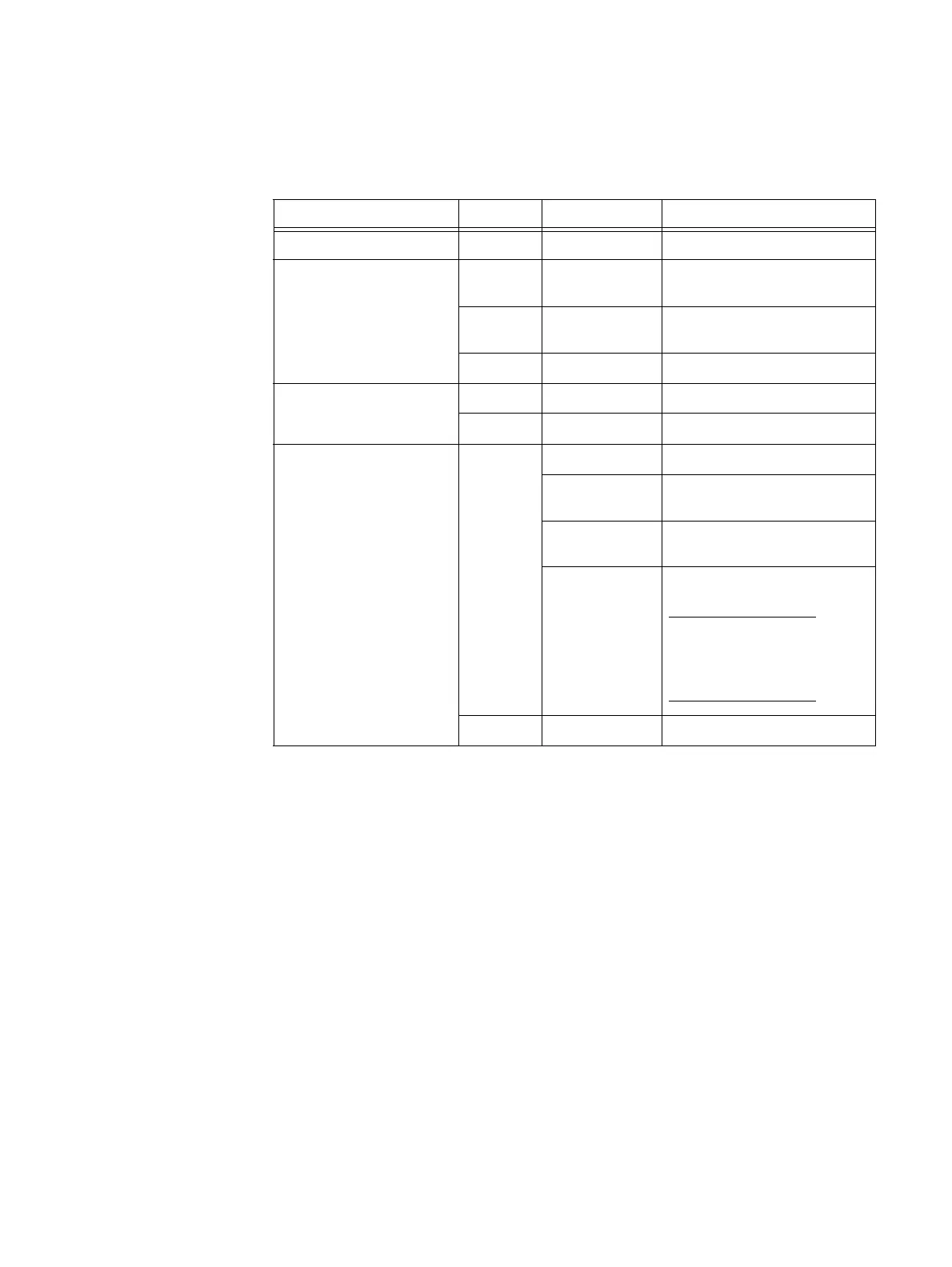
Table 37 describes the VNX5400 platform DAE and the 3.5-inch disk drive status LEDs
Rear view
On the rear of the VNX5400 platform, the 3U, 15 (2.5- or 3.5-inch) disk drive DAE includes
the following components:
◆ Two LCCs (A and B)
◆ Two power supply/cooling modules (A and B)
Figure 61 on page 83 shows an example of the rear view of a 3U, 15 (3.5-inch) disk drive
DAE.
Table 37 3U, 15 (3.5-inch) DAE and disk drive LEDs
LED Color State Description
DAE fault (see location 2) Amber On Fault has occurred
DAE power (see location 3) Green On Powering and powered up with
back-end bus running at 2 Gb/s
Blue On Powering and powered up with
back-end bus running at 6 Gb/s
— Off Powered down
Disk drive fault
(see location 4)
Amber On Fault has occurred
— Off No fault has occurred
Disk drive on/activity
(see location 5)
Green On Powering and powered up
Blinking, mostly
on
Disk drive is on with I/O activity
Blinking at
constant rate
Disk drive is spinning up or down
normally
Blinking Disk drive is powered up but not
spinning
Note: This is a normal part of the
spin-up sequence, occurring
during the spin-up delay of a
slot.
— Off Disk is powered down

 Loading...


