DPSI RV Family Operating Instructions Version 2.0
Page 22 of 48
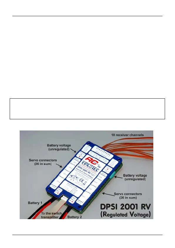
Two commercial battery controllers can be plugged directly to the
backside of the switch using JR Uni-Connectors. The inscription “B1”
stands for battery 1 and “B2” for battery 2. This enables additional
optical voltage monitoring of the batteries. When using this type of
battery controller, you must ensure that the required number of cells is
correctly set.
If the pin is plugged into the black (off) socket, the entire receiver set is
switched off (any battery controllers that may be connected as well). In
switched-off position, the batteries will not discharge. The minimum
“quiescent current” of the DPSI RV is far below the self-discharge of
the connected batteries. Theoretically, it would take 274 years for the
quiescent current to discharge a 2.4Ah battery.
Hint:
The additional outputs of the DPSI RV Mini ESP series and the DPSI 2001 RV
which carry unregulated voltage are switched on and off by the electronically
switches of the DPSI RV, too.