EMCS User Guide
- 25 -
9.2 LEDs and Indicators
The EMCS touchpad attached to the inner door has:
13 cab phone icon indicators (in-conversation = green; pending action = orange;
fault = red; no phone detected = off)
3 programming keypad LEDS
o Wake (programming keypad awake = green)
o Program mode (green)
o Line test (test call in progress = green)
4 alarm status indicators (as described in 4.2)
o POWER (mains off = red)
o BATTERY (alarm pending = red)
o PHONE LINE (fault = red)
o PLM (alarm pending = red)
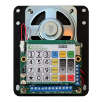
There are 13 PCB-mounted LEDs present on the main circuit board under the service
panel. These LEDs provide essential diagnostic and status information at a glance:
1. Heartbeat D5 (pulsing green) (located above the large capacitors in the bottom
left quadrant of the main board)
2. Power (input PWR present = green)
3. 3 x PLM (normal = green; fault = off) (located below the silkscreen label “TO
EMC-ALRM”)
4. PLM-PWR (output power present = green)
5. 6 x Video Triggers (idle = off; in-use = green)
6. 1 x Video Reset (idle = on; any cab in-use = off)
10. Ordering
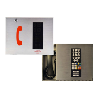
Model and description
EMCS-BASE - High Rise for 6 cabs + 3 PLM groups + 6 video triggers in ss enclosure
with handset
EMCS-MR - EMCS-BASE without handset for machine room mounting
EMCS-OEM - EMCS-BASE without enclosure for mounting in lobby panel
EMCS-FR - EMCS-BASE in ss enclosure with handset and 2 or 3 position Fire Recall
switch
EMCS-EXP - for expansion to 7-12 cabs + 4-6 PLM groups + 7-12 video triggers