14. Wait for 30 - 60 seconds to let the coupling fluid spread more evenly on the surface.
15. Insert the transducer capsule into the transducer stalk while aligning the anti-
rotation pin on the capsule with the slot on the inner surface of the stalk.
16. Make sure that the indicator ring on the transducer capsule is flush with the end of
the transducer stalk to ensure the capsule is set to the correct length (see Table
3-2).
17. Hand-tighten the transducer retainer onto the stalk.
18. Follow Section 3.5.2 to install the transducer assembly in a meter body.
3.7 Transducer cable removal and installation
Daniel 3410 Series Ultrasonic Gas Flow Meters have red transducer cables that plug
directly in the back of the transformer retainer.
Note
Make a note of the exiting cabling path layout to allow proper tie-wrap configuration later
in this procedure.
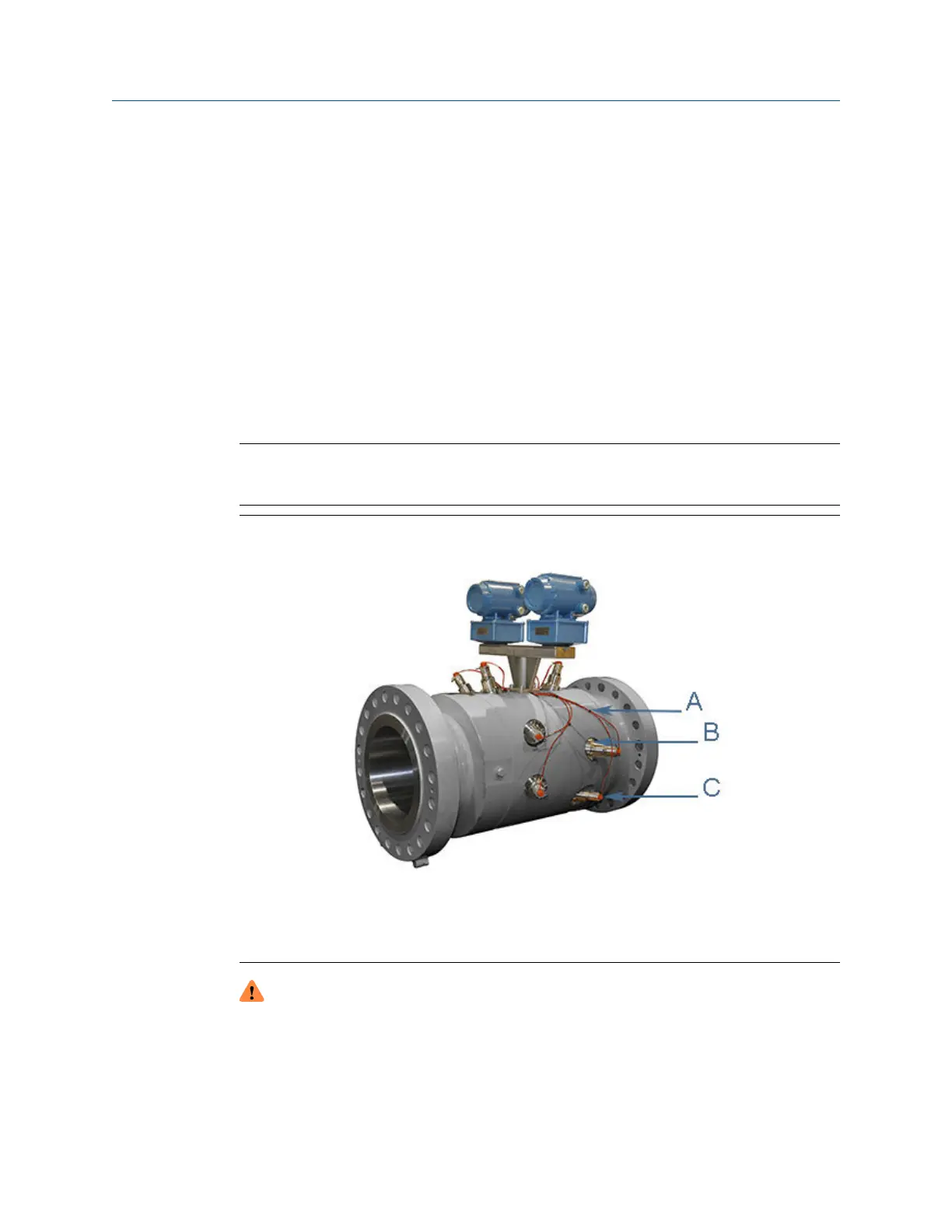
Figure 3-14: Daniel 3410 Series Ultrasonic Gas Flow Meter transducer cables and
ports
A. Cable ties
B. 3410 Series Ultrasonic Meter transducer port
C. Transducer assembly
WARNING
CRUSHING HAZARD
During meter installation or removal, always place the unit on a stable platform or
surface that supports its assembled weight.
Failure to comply could allow the meter to roll, resulting in serious injury or equipment
damage.
Maintenance and Troubleshooting manual Meter repairs
P/N 3-9000-791 August 2021
Maintenance and Troubleshooting manual 67

 Loading...


