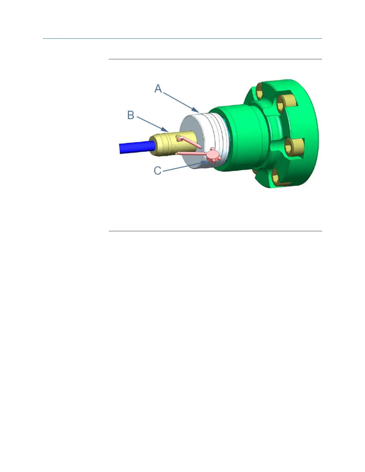
Figure 3-19: Transducer cable nut, chordset and security seal
A. Transducer cable nut
B. Transducer cable chordset
C. Security wire seal
26. Twist and adjust wire removing all slack and seal. Remove excess wire (see Figure
3-19).
27. If required by the site operations manager, have an electrician fully test the
connections. After the Acceptance Test is witnessed and approved, seal the
conduit.
28. Power down the system and apply the sealing compound to the conduit and allow
to set in accordance with manufacturer specifications.
3.8 Replace the meter electronics
The following procedure should be performed by a qualified service technician or trained
personnel. Observe all warning labels on the meter before starting this procedure.
The Daniel 3410 Series Gas Ultrasonic Flow Meter Transmitter Electronics Enclosure
consists of the following:
• CPU Module assembly (P/N 1-360-03-010)
• Optional I/O module (RS-232 or RS-485)
• Expansion I/O module
• I.S. Barrier Board (P/N 360-03-004)
• Power Supply (P/N 360-03-003)
• Backplane Board (P/N 360-03-007)
The Daniel 3410 Series Gas Ultrasonic Flow Meter Base Enclosure consists of the following:
Maintenance and Troubleshooting manual Meter repairs
P/N 3-9000-791 August 2021
Maintenance and Troubleshooting manual 73

 Loading...


