• Acquisition Module (P/N 1-360-03-008) (T-21, T-22, T-41, T-200)
• Transducer Cable (5FT P/N 1-360-03-232, 15FT P/N 1-360-03-233)
Should the Daniel 3410 Series Ultrasonic Gas Flow Meter require disassembly in the field
(i.e., check boards, change switch settings, or replace boards), to prevent electrostatic
damage to the electronic boards, always use a ground strap while handling the circuit
boards. If one is not available, ensure you are electrically discharged before touching the
boards by first touching a metal surface such as a ground lug on the meter or a table.
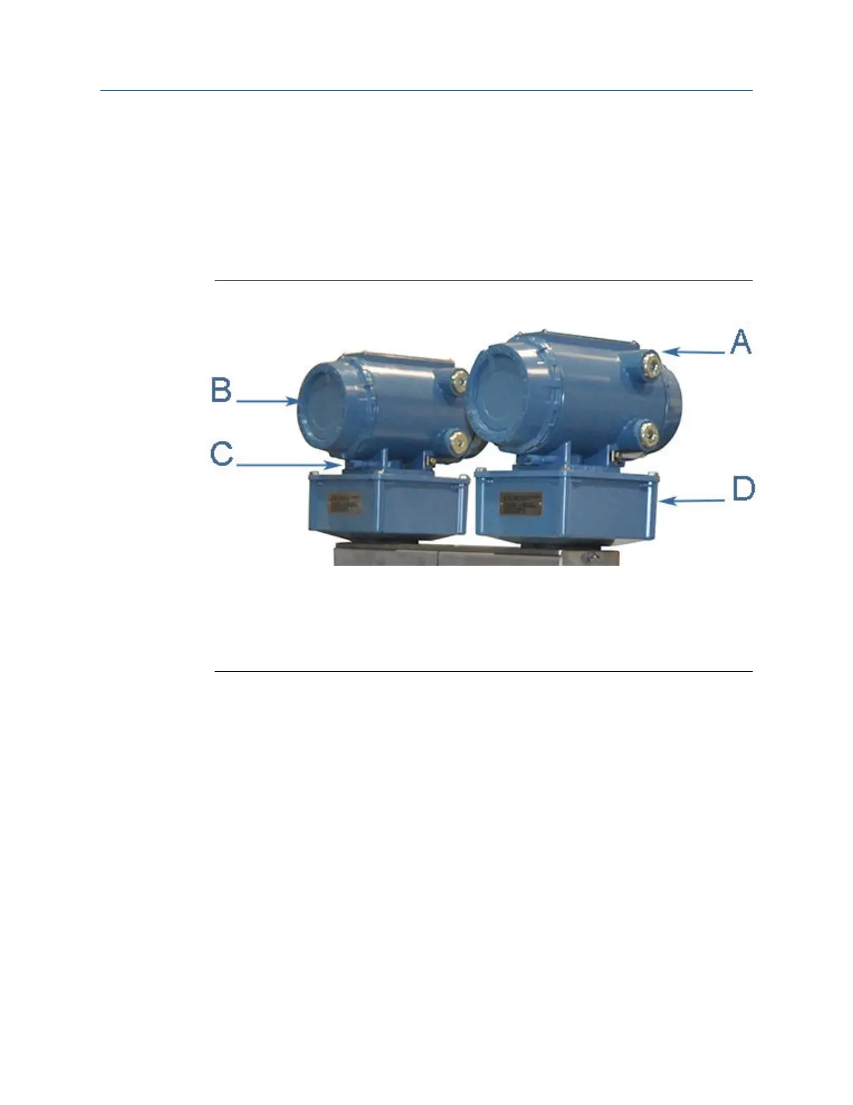
Figure 3-20: 3410 Series electronics
A. Terminal end of Transmitter Electronics Enclosure
B. Backplane board location
C. End cap security latch
D. Base enclosure with Acquisition Module
3.8.1
Replace CPU module or Optional I/O module
Procedure
1. Remove power to the meter.
2. Disconnect security seals on the Transmitter Electronics Enclosure (see Figure
3-17), loosen the end cap security latches using a 3 mm Allen wrench (see Figure
3-16) and remove end cap from the terminal end of the Transmitter Electronics
Enclosure.
3. Disconnect the CPU Module terminal blocks (or the optional I/O Module terminal
blocks) if replacing the CPU Module (terminal end of the enclosure) or the Optional
I/O Module.
Meter repairs Maintenance and Troubleshooting manual
August 2021 P/N 3-9000-791
74 Models 3415, 3416 and 3417 GUSM

 Loading...


