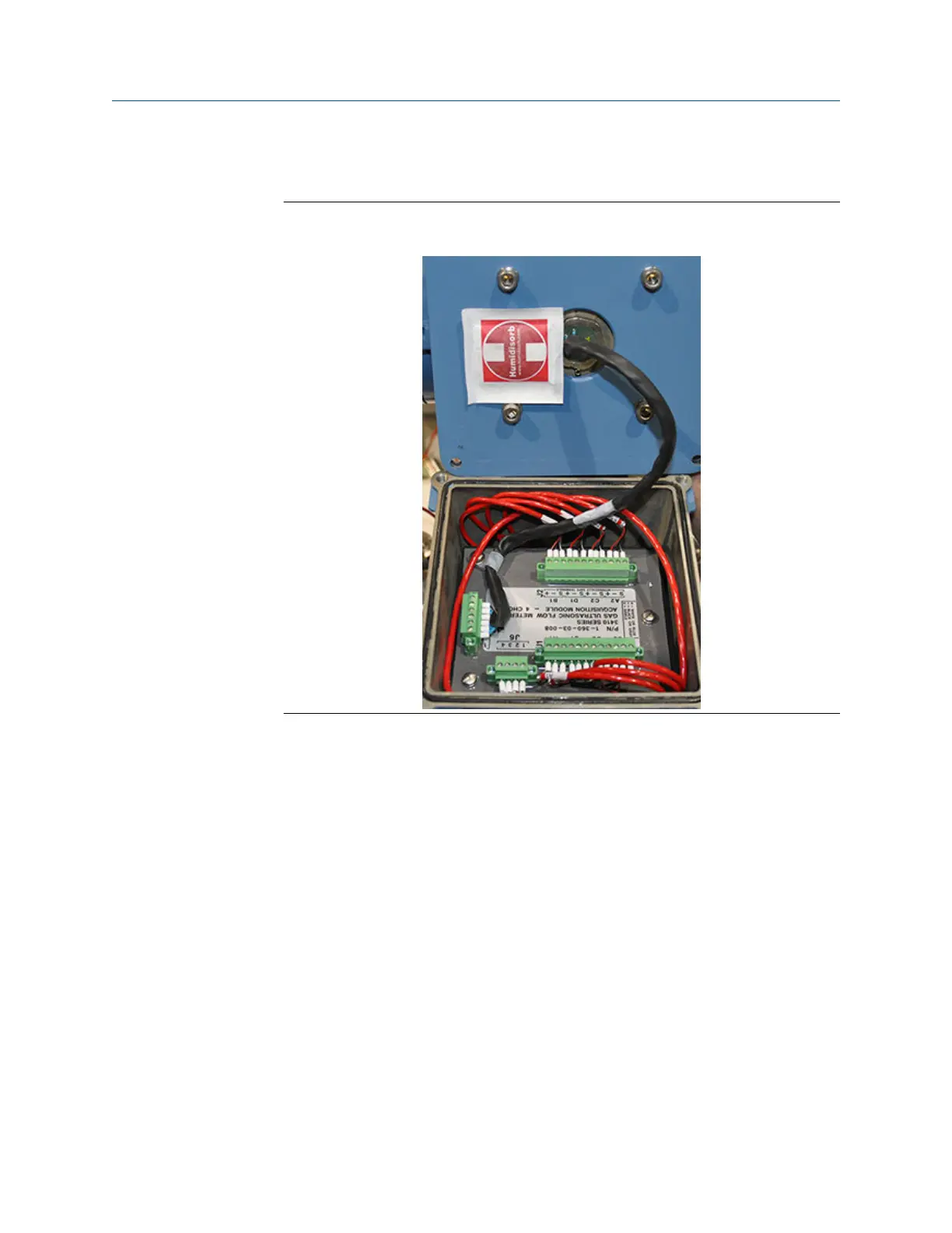
block J1 and J2 as shown in Figure 3-16 Ultrasonic Meter Acquisition Module
wiring.
Figure 3-16: Models 3415, 3416, 3417 Ultrasonic Meter Acquisition Module
wiring
6. Only connect wires for Chords A1, A2, B1 and B2 for 3416 and 3417 meter
applications or A1 and A2 for 3415 meter applications. The relative position of the
contacts is shown on the Acquisition Module label adjacent to the terminal block.
a) When terminating the connector wires, ensure that the contacts clamp on
the bare wires and not on the wire insulation.
b) Leave the connector plugged into the Acquisition Module while terminating
the individual wires.
7. Tighten the cable gland once the transducers are wired correctly, so that the
transducer cable is held securely in place. Pull the cable back through the gland to
remove the slack and configure the cable to follow the same path of the existing
cable (see Figure 3-16) and note in Transducer cable removal and installation.
8. Repeat Step 1 through Step 7 if you are replacing other cables.
9. Once all of the cables are replaced, dress with tie wraps (P/N 2-4-9158-001) in
groups of two. Once all of the cables are replaced; A1 and C1, D1 and B1, A2 and C2,
D2 and B2. Install one cable tie three inches from the Base Enclosure and another
near the point the cables start to bend and separate out into their respective port
(see Figure 3-16).
Meter repairs Maintenance and Troubleshooting manual
August 2021 P/N 3-9000-791
70 Models 3415, 3416 and 3417 GUSM

 Loading...


