10. Inspect the Transmitter Electronics Enclosure gasket for wear and replace it if
necessary.
11. Lubricate it with Molykote 111
(2)
(P/N 2-9-9960-135) if replacing the gasket.
12. Prop the Transmitter Electronics Enclosure at an angle on top of the Base Enclosure.
13. Plug the Acquisition cable terminal block to J3 on the Acquisition Module. Use a flat
blade screw driver and securely tighten the terminal block mounting screws to the
Acquisition Module.
14. Wrap the excess cable around the Acquisition Module below the lip of the Base
Enclosure (this prevents pinching the cable when the Transmitter Electronics
Enclosure is installed).
15. Attach one desiccant pack to the underside of the Base Enclosure cover.
16. Place the Transmitter Electronics Enclosure onto the Base Enclosure. Rotate the
Transmitter Electronics Enclosure until the mounting holes are correctly aligned
with the holes in the Base Enclosure.
17. Install the two hex head bolts with a 6 mm Allen wrench to secure the Transmitter
Electronics Enclosure to the Base Enclosure.
18. Reattach the external ground wire to the ground lug, reconnect the conduit, and
power the meter.
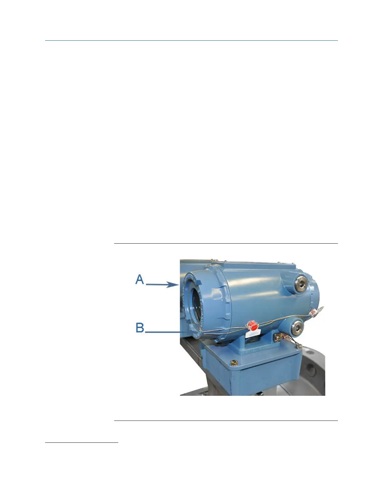
19. If required, install the security seal wire into and through one of the two holes in the
end cap. Choose holes that minimize counterclockwise rotation of the end cap
when the security wire is taut (maximum wire diameter 0.078 inch; 2.0 mm).
Figure 3-17: Transmitter Electronics Enclosure security seals
A. Transmitter electronics enclosure endcap
B. Security seals
(2)
Molykote 111 is a trademark of Dow Corning Corporation, U.S.A.
Maintenance and Troubleshooting manual Meter repairs
P/N 3-9000-791 August 2021
Maintenance and Troubleshooting manual 71

 Loading...


