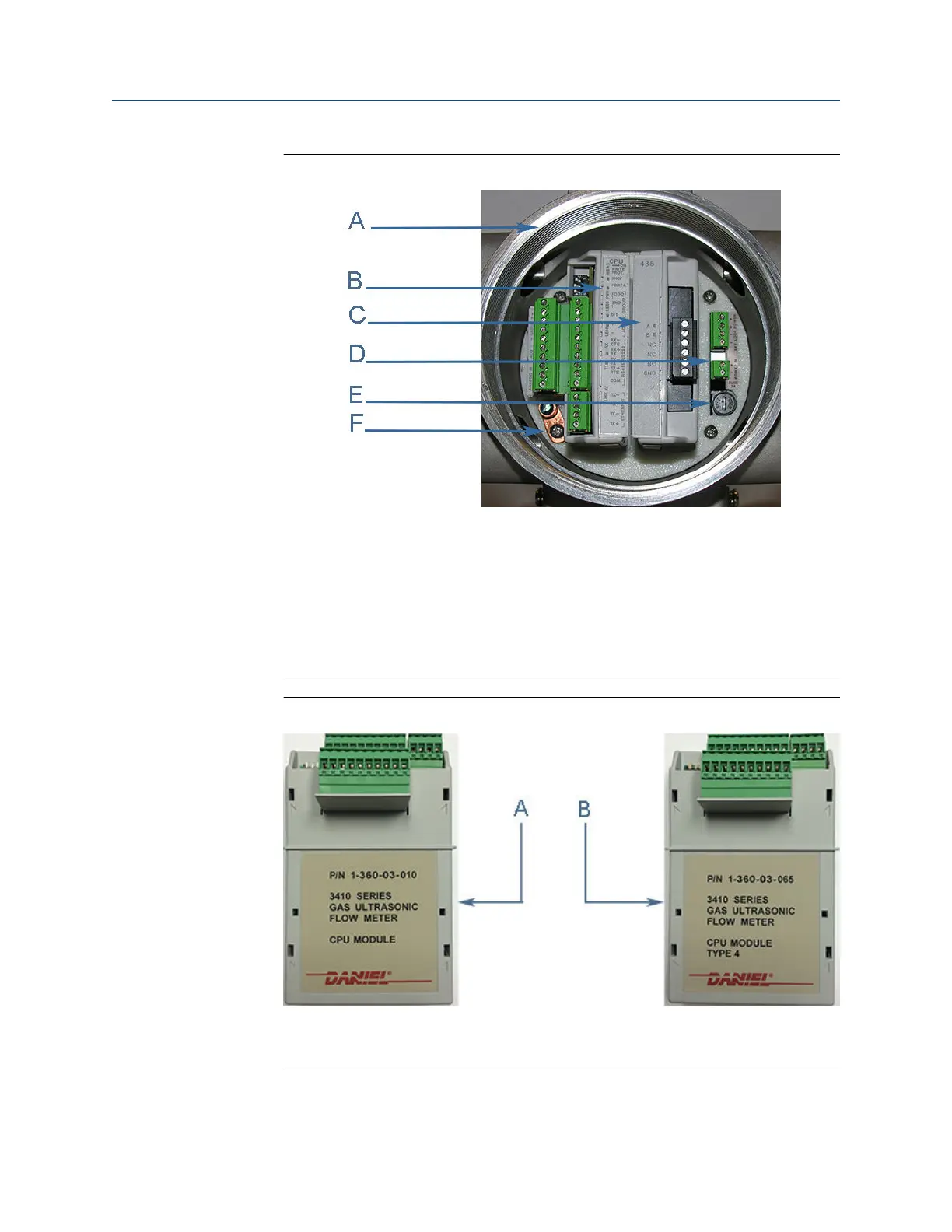
Figure 3-21: CPU or I/O Module replacement
A. Terminal end of Transmitter Electronics Enclosure
B. CPU Module
C. Optional I/O Module
D. Power Supply board
E. Fuse
F. Internal chassis ground
Figure 3-22: CPU module Type 2 and Type 4
A. CPU Module Type 2 - side label
B. CPU Module Type 4 - side label
Maintenance and Troubleshooting manual Meter repairs
P/N 3-9000-791 August 2021
Maintenance and Troubleshooting manual 75

 Loading...


