4. Grasp the outer ends of the module you want to replace and pull it out of the
enclosure.
5. Insert the new CPU Module or I/O Module into the enclosure and firmly push until
the board is fully seated into the Backplane Board connectors and the lock is
engaged.
6. Replace the terminal blocks for the CPU Module and/or the Optional I/O Module
and verify the tightness of the terminals with a 3 mm flat blade screw driver.
Important
If changing from Type 2 to Type 4 CPU, note wiring changes required for AO2 and
Group 2 Outputs.
7. If you are not replacing other electronics, replace the end cap and security latches
(requires a 3 mm Allen wrench). If required, install the security seal wire into and
through one of the two holes in the end cap.
a) Choose holes that minimize counterclockwise through one of the two holes
in the end cap.
b) Choose holes that minimize counterclockwise rotation of the end cap when
the security wire is taut (maximum wire diameter.078 inch; 2.0 mm).
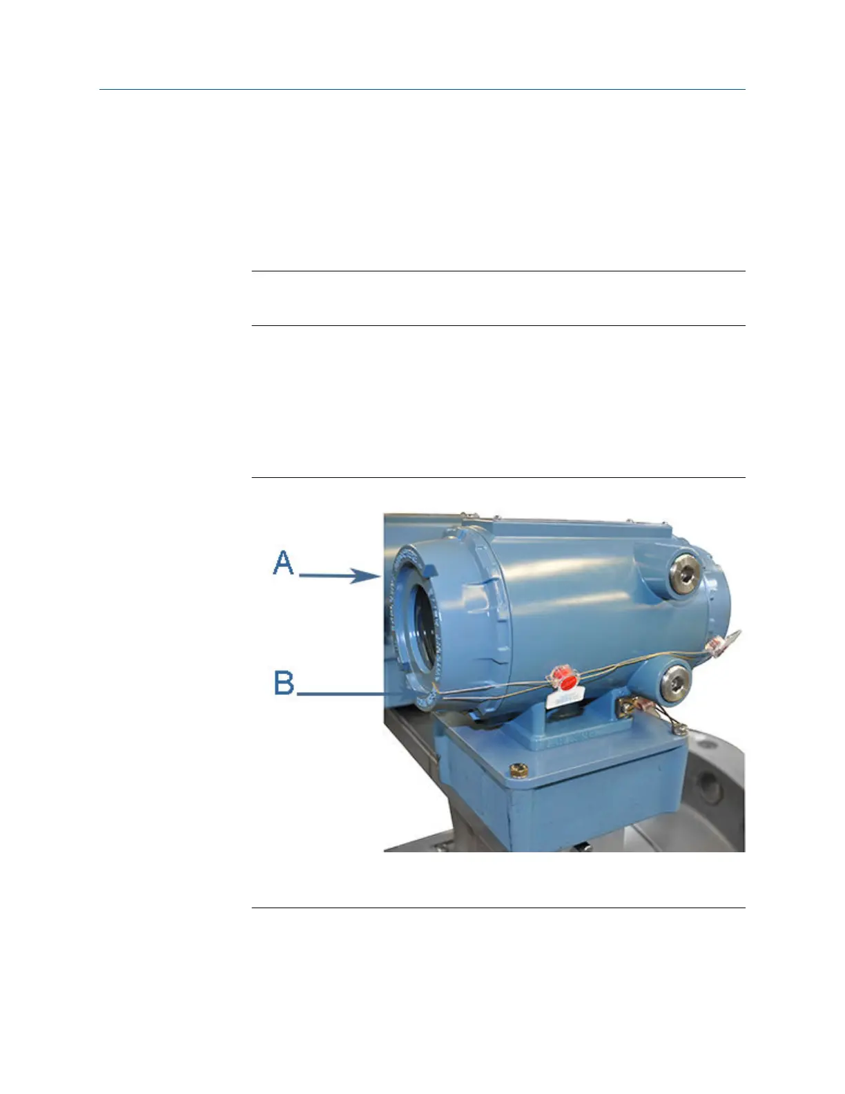
Figure 3-23: Transmitter electronic enclosure security seals
A. Transmitter Electronics Enclosure end cap
B. Security wire seals
8. Adjust the security wire, removing all slack and thread into the lead seal.
9. Cut wire ends to remove excess wire.
Meter repairs Maintenance and Troubleshooting manual
August 2021 P/N 3-9000-791
76 Models 3415, 3416 and 3417 GUSM

 Loading...


