• X7E1 socket (5): fieldbus connection
• X7E2 socket (6): fieldbus connection
• X1S plug (7):
• 24VDC power supply for bus coupler
• Ground screw (8): functional earth
The tightening torque for the connection plugs and sockets is 1.5Nm +0.5.
The tightening torque for the M4x0.7 nut (SW7) on the ground screw is 1.25Nm
+0.25.
Fieldbus connection
The X7E1 (5) and X7E2 (6) fieldbus connections are designed as integrated M12
sockets, female, 4-pin, D-coded.
u See Table6 for the pin assignments for the fieldbus connections. The view
shown displays the device connections.
Table4: Pin assignments of the fieldbus connections
Pin X7E1 (5) and X7E2 (6) sockets
Pin 1 TD+
Pin 2 RD+
Pin 3 TD–
Pin 4 RD–
Housing Ground
The AESseries bus coupler for EtherNet/IP has a 100Mbit full duplex 2-port
switch, so that several EtherNet/IPdevices can be connected in series. As a result,
the controller can be connected to either fieldbus connection X7E1 or X7E2. Both
fieldbus connections are identical.
Fieldbus cable
NOTICE
Danger caused by incorrectly assembled or damaged cables!
The bus coupler may be damaged.
u Only use shielded and tested cables.
NOTICE
Faulty wiring!
Faulty wiring can lead to malfunctions as well as damage to the network.
1. Comply with the EtherNet//IP specifications.
2. Only a cable that meets the fieldbus specifications as well as the connection
speed and length requirements should be used.
3. In order to assure both the protection class and the required strain relief,
the cable and plug assembly must be done professionally and in accor-
dance with the assembly instructions.
4. Never connect the two fieldbus connections X7E1 and X7E2 to the same
switch/hub.
5. Make sure that you do not create a ring topology without a ring master.
Power supply
DANGER
Electric shock due to incorrect power pack!
Danger of injury!
1. Only use the following power supply for the bus coupler:
- 24VDC SELV or PELV circuits, each with a DC fuse that can interrupt a cur-
rent of 6.67A within max. 120s, or
- 24VDC circuits meeting the requirements for energy-limited circuits as
described in section9.4 of UL standard UL61010-1, third edition, or
- 24VDC circuits meeting the requirements for power-limited power
sources in accordance with section2.5 of UL standard UL60950-1, second
edition, or
- 24VDC circuits meeting the requirements of NEC ClassII in accordance
with UL standard UL1310.
2. Make sure that the power supply of the power pack is always less than
300VAC (outer conductor – neutral wire).
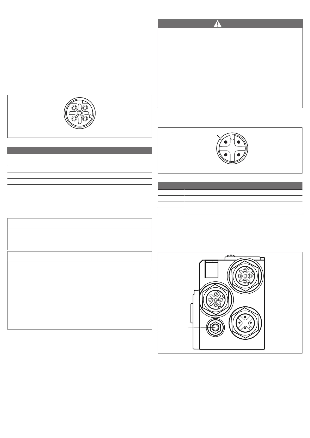
The X1S power supply connection (7) is an M12 plug, male, 4-pin, A-coded.
u See Table7 for the pin assignments for the power supply. The view shown dis-
plays the device connections.
Table5: Power supply pin assignments
Pin X1S plug
Pin 1 24VDC sensor/electronics power supply (UL)
Pin 2 24VDC actuator voltage (UA)
Pin 3 0VDC sensor/electronics power supply (UL)
Pin 4 0VDC actuator voltage (UA)
• The voltage tolerance for the electronic components is 24VDC ±25%.
• The voltage tolerance for the actuator voltage is 24VDC ±10%.
• The maximum current for both power supplies is 4A.
• The power supplies are equipped with internal electrical isolation.
Functional earth connection
u To discharge the EMC interferences, connect the FE connection (8) on the bus
coupler via a low-impedance line to ground.
The cable cross section must be designed according to the application.
4.1.2 LED
The bus coupler has 6LEDs.
The table below describes the functions of the LEDs. For a comprehensive de-
scription of the LEDs, see section g11.LED Diagnosis on the Bus Coupler.
AVENTICS™ EtherNet/IP | R412018139-BAL-001-AG | English 30

 Loading...


