Operation without EDS file
You can also operate the system without an EDS file.
1. For this, calculate the incoming and outgoing data lengths as described in Ta-
ble 9.
2. Enter the following values in the PLC configuration program for a class1 con-
nection:
Connection:
Master → slave: point-to-point
Slave → master: multicast
Connection points:
Master → slave: “101” and as data length “output data length”
Slave → master: “102” and as data length “input data length”
Configuration: “1” and as data length “0”
5.3 Configuring the Bus Coupler in the Fieldbus System
Before you can configure the individual components of the valve system, you
need to assign an IPaddress to the bus coupler using your PLC configuration soft-
ware. In most cases, a DHCPserver assigns the address during commissioning
and subsequently permanently assigns it to the device.
1. Assign a unique IP address to the bus coupler using the planning tool
g9.3.Assigning IP Address and Subnet Mask.
2. Configure the bus coupler as a slave module.
5.4 Configuring the Valve System
5.4.1 Module sequence
The input and output data used by the modules to communicate with the con-
troller consist of a byte string. The lengths of the valve system input and output
data are calculated from the number of modules and the data width of the indi-
vidual module. The data is only counted in bytes. If a module has less than 1 byte
of input or output data, the left-over bits are “stuffed” to the byte boundary us-
ing non-information bits.
Example: A valve driver board, 2x, with 4 bits of user data occupies 1byte in the
byte string, since the remaining 4 bits are stuffed with non-information bits. The
data of the next module therefore starts after a byte boundary.
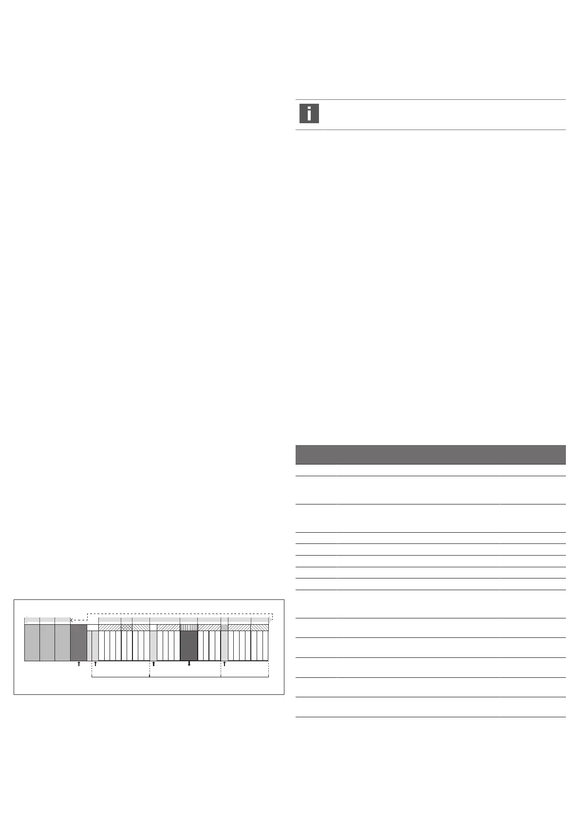
In the example (see Fig.3), the modules are numbered to the right of the bus
coupler (AES-D-BC-EIP) in the valve zone, starting with the first valve driver board
(module1) and continuing to the last valve driver board on the right end of the
valve unit (module9).
Bridge cards are not taken into account. Supply boards and UA-OFF monitoring
boards occupy one module (see module7 in Fig.3). The supply boards and UA-
OFF monitoring boards do not add any bytes to the input and output data. How-
ever, they are also counted, since they have diagnostic data, which is transferred
at the corresponding module position. The data length for pressure regulators
can be found in the operating instructions for AV-EP pressure regulators
(R414007537).
The numbering is continued in the I/O zone (module10 to module12 in Fig.3).
There, numbering is continued starting from the bus coupler to the left end.
The bus coupler’s parameter data is annexed to the output data in the byte chain.
The bit assignments of the bus coupler are described in section g5.5.Setting the
Bus Coupler Parameters.
The diagnostic data of the valve system is 8 bytes in length and is appended to
the input data. The structure of this diagnostic data is described in Table14.
M1/OB1 M3/OB3 M4/OB4 M6/OB6M5/OB5 M8/OB7M7/– M9/OB8M10/IB1M11/IB2M12/OB8
8DI8M8
8DI8M8
8DO8M8
M2/OB2
AES-D-BIC-EIP
P P UA
S1 S2 S3
UA A
AV-EP
(M)
Fig.3: Numbering of modules in a valve system with I/O modules
S1 Section 1 S2 Section 2
S3 Section 3 P Pressure supply
UA Power supply M Module
A Single pressure control working con-
nection
AV-
EP
Pressure regulator with 16 bits of in-
put and output data
IB Input byte OB Output byte
- Neither input nor output byte
The symbols for the valve zone components are explained in sec-
tiong12.2.Valve Zone.
Example
Fig.3 shows a valve system with the following characteristics:
• Bus coupler
• Section1 (S1) with 9valves
– Valve driver board, 4x
– Valve driver board, 2x
– Valve driver board, 3x
• Section2 (S2) with 8valves
– Valve driver board, 4x
– Pressure regulator with 16 bits of input and output data
– Valve driver board, 4x
• Section3 (S3) with 7valves
– Supply board
– Valve driver board, 4x
– Valve driver board, 3x
• Input module
• Input module
• Output module
The PLC configuration key for the entire unit is thus:
423–4M4U43
8DI8M8
8DI8M8
8DO8M8
The data lengths of the bus coupler and the modules are shown in Table9.
Table7: Calculation of the valve system data lengths
Module
number
Module Output data Input data
1 Valve driver board, 4x 1 byte of user data –
2 Valve driver board, 2x 1 byte
(4bits of user data plus
4filler bits)
–
3 Valve driver board, 3x 1 byte
(6bits of user data plus
2filler bits)
–
4 Valve driver board, 4x 1 byte of user data –
5 Pressure regulator 2 bytes of user data 2 bytes of user data
6 Valve driver board, 4x 1 byte of user data –
7 Electrical supply – –
8 Valve driver board, 4x 1 byte of user data –
9 Valve driver board, 3x 1 byte
(6bits of user data plus
2filler bits)
–
10 Input module (1byte of user
data)
– 1 byte of user data
11 Input module (1byte of user
data)
– 1 byte of user data
12 Output module (1byte of
user data)
1 byte of user data –
– Bus coupler 1byte of parameter
data
8bytes of diagnostic
data
Total length of output
data: 11 bytes
Total length of input
data: 12 bytes
The total length of the output data in the example configuration is 11bytes. Of
this, 10 bytes are the module output data and 1 byte is the bus coupler parame-
ter byte.
AVENTICS™ EtherNet/IP | R412018139-BAL-001-AG | English 32

 Loading...


