2
INSTALLATION
New Construction Rough-In
•Fastenelectricalconnectionbox(ECB)asrequired
per local electrical code on side of stud.
•Drillone1-inchholeinbaseplateforsingle-cable
installation and two 1-inch holes for two-cable
installation.
•Threadpull-cord(notprovided)throughhole(s)
inbaseplateandincorrespondingholesinECB.
SecurethepullcordsintheECB.
Tie floor ends of pull-cord and fasten to floor.
•Installtheguardplate(notprovided)overthe
hole for the cold leads and sensor wire before
drywalling.
•InstallguardplateasshowninFigure1.
Thermostat Installation
•Ensurethesupplybranchcircuithasbeen
disconnected / de-energized.
•PullsensorwireintoECBandsecuretothefloor.
See Figure 2. The sensor must not cross or overlap
anyothercableonthefloorANDmustbe
embedded in the cementituous based mortar in
the same manner as the heating cables.
•Thefloortemperaturesensorwirecanbe
extendedtoamaximumof50feetwithULorCSA
recognized wire 22 AWG rated for 300 V.
•Preparethethermostatforinstallation:
1. Remove the thermostat and screws from
packaging.
2.LoosenthescrewonthebottomoftheFrontPanel
andlifttheFrontPanelasshowninFigure3.
3.Trimexcesslengthofsupplybranchcircuit,
cold lead and temperature sensor cables, as
necessary, leaving about 6” projecting from
theECB,seeFigure4.Mostheatingcablesare
provided with identification labels attached to the
end of the cold leads – ensure that these labels
remainonthecoldleadinsidetheECB.
4.Prepareeachheatingcable/coldleadfor
connection/splicingandconnectionperFigure5
or Figure 6, as applicable.
5.PreparethesensorwireperFigure5orFigure6,as
applicable.Usescrewdriverforconnectiontothe
sensor wire connections (black and white wires) to
correspondingBLKandWHTterminals.
6.NeatlyfoldallwiringintoECBandfasten
thermostatwith#6-32screwsprovided.Donot
applyexcessiveforcetothethermostat.Apply
firm but continuous force until the screws can be
fully seated.
7. Align the thermostat power base, then finish
tightening the two screws.
8.HooktheFrontPanelunittothetopofthePower
Baseunit,swingdownandpresstheFrontPanel
intothePowerBaseunitslightly,tightenthescrew
at the bottom of the unit.
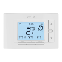
A. Button Explanation
LCD Display–Largescalereadoutwithbluecolor
backlight which indicates the operational status of
the thermostat.
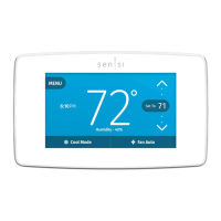
On/Off Button – Allows easy selection switching On
or Off the thermostat.
Event/Program Button–Pressingthisbuttononce
enters the thermostat into programming mode or
cycles through the program events in programming
mode.
Next/Save Button –Pressingthisbuttonacceptsthe
modifiedsettingandcyclestheprogramtothenext
parameter.
-Pressingandholdingthisbuttondownfor2seconds
saves all changes that have been accepted during
thecurrentprogrammingcyclesandexitsthe
programming mode.
Back/Cancel Button –Pressingthisbuttonmoves
the programming back to the previous setting
parameter.
A. Button Explanation
Figure 1
Guardplate
LCD Display
GFCI Test
Event/Program
Settings
Next/Save
Up
Down
Hold
GFCI Reset
On/Off
Back/Cancel

 Loading...