Do you have a question about the Emerson EIM E796 M2CP and is the answer not in the manual?
Details on the high-quality lubricant used and its replacement.
Annual check procedure for EIM actuators, including electrical and mechanical inspection.
Explanation of pressure build-up in the gearbox and the use of a relief vent fitting.
Guidelines for storing actuators on-site for less than one year.
Procedures for storing actuators for more than one year, emphasizing protection.
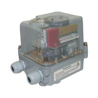
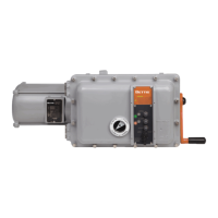
Steps for connecting electrical wiring to the M2CP terminals and circuit breaker.
Instructions for installing the actuator onto a threaded valve stem, including lockpin and stem nut.
Details on using mounting screws for actuator attachment, including thrust spool and spline bushing.
Procedure for assembling the actuator to a quarter-turn valve, including stop setting.
Pre-adjustment steps including valve positioning and power phase verification.
Detailed steps for adjusting the Open Limit Switch (LSO) for proper valve travel.
Procedure for adjusting the Close Limit Switch (LSC) to define the closed valve position.
Instructions for setting intermediate limit switches if they are part of the actuator configuration.
Guidance on setting limit switches for torque-seated valves for accurate indication.
Process for calibrating torque switches to prevent actuator damage from over-torque.
Procedure for setting the Open Torque Switch (TSO) for over-torque protection.
How to adjust rotation limits using pins to restrict actuator movement.
Steps to calibrate the Mechanical Dial Position Indication (MDPI) and potentiometer.
Details on gear reduction assembly and potentiometer for quarter-turn models.
Explanation of various symbols used in EIM wiring diagrams and their components.
| Brand | Emerson |
|---|---|
| Model | EIM E796 M2CP |
| Category | Controller |
| Language | English |