2
1
2
1
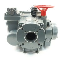
4 STROKE ADJUSTMENT
TheELQ-seriesactuatorshavetwowaysoflimiting
thestroke:
• Electricallylimitingthestrokebymotorlimitswitch
setting.
• Mechanicallylimitingthestrokebylimitstop
screws(whentheactuatorisundermanualop-
eration).
1 = open
2 = closed
4.0.1 Electrically limiting the stroke by motor limit switch setting.
4.0.2 Mechanically limiting the stroke by limit stop screws
4.1 Setting of switches and mechanical
limit stops
4.1.1 Factory settings
ThenominalrotationoftheELQ-actuatorisfactory
set.Ifdesiredadjustthemotorandlimitswitchesand
themechanicallimitstopsafterinstallingtheELQ-
actuatoronthevalve.
(Forconnectinglimitswitchsignalsforpositionindi-
cation,see§5.2)
Table 4.1 Factory settings
Nominalrotation 90°
Motorandlimitswitches +1° ateachend
Mechanicallimitstops +5° ateachend
Important
Duringoperationthesequenceofreach-
ingthevariousswitches/stopsattheendof
strokeshouldbe;
1e Limitswitches
2e Motorswitches
3e Limitstops
4.1.2 Procedure
1. Mounttheactuatorontoavalve.
"Open" position:
2. Movethevalveawayfromthefullyopenposition
withthemanualoverridehandwheel.
3. Turnthe“open”mechanicalstopscrewout
(CCW)4turns.
4. Movethevalvetothefullyopenpositionwiththe
manualoverridehandwheel.
5. Turn“motorswitchopen”-cam(CW)untilswitch
trips.
Forpositionindicationsetthelimitswitchesasfol-
lows:
Turn“Limitswitchopen”-cam(CW)untilswitchtrips.
6. Turnthe“open”mechanicalstopscrewin(CW)
untilanobstructionisfelt(donotforce)then
back-off3turnsandlockthemechanicalstop
screwwiththelocknut.
 Loading...