Chapter 3 Installation and Wiring 29
EV2000 Series Universal Variable Speed Drive User Manual
Category Terminal Name Functions Specifications
Power
supply
P24 +24V power supply
Provide +24V power supply for
external equipment.
Maximum output current:
200mA
PLC
Common terminal of
multi-function input
terminal
Common terminal of multi-function
input terminal (short circuit with P24)
Common terminal of X1~X8.,
FWD and REV. PLC is isolated
with P24.
COM
Common terminal of
+24V power supply
Total 3 common terminals, which are
used in conjunction with other
terminals.
COM is isolated with CME and
GND.
CME
Common terminal of Y1
and Y2 output
Common terminal of multi-function
Y1 and Y2 output
(Short circuit with COM by
manufacturer)
Shielding PE Shielded GND
Grounding terminal connected to
shielding layer
Connected to PE inside the
drive
1) Wire connections multi-function input terminals,
terminals FWD and REV:
EV2000 multi-function input terminal uses a full-bridge
rectifying circuit as shown in Fig. 3-. PLC is the common
terminal of terminals X1~X8, FWD and REV. The current
flows through terminal PLC can be pulling current, and
also the feeding current. Wire connections X1~X8, FWD
and REV is flexible and the typical wiring is shown
below:
A) Method 1 of connections (Dry contacts)
①If internal 24V power supply is used, the wiring is
shown in Figure 3-22.
+24V
、X1 X2
. . . X8
、FWD
REV
PLC
EV2000
+5V
COM
P24
R
+
-
K
power
source
Fig. 3-22 Using internal 24V power supply
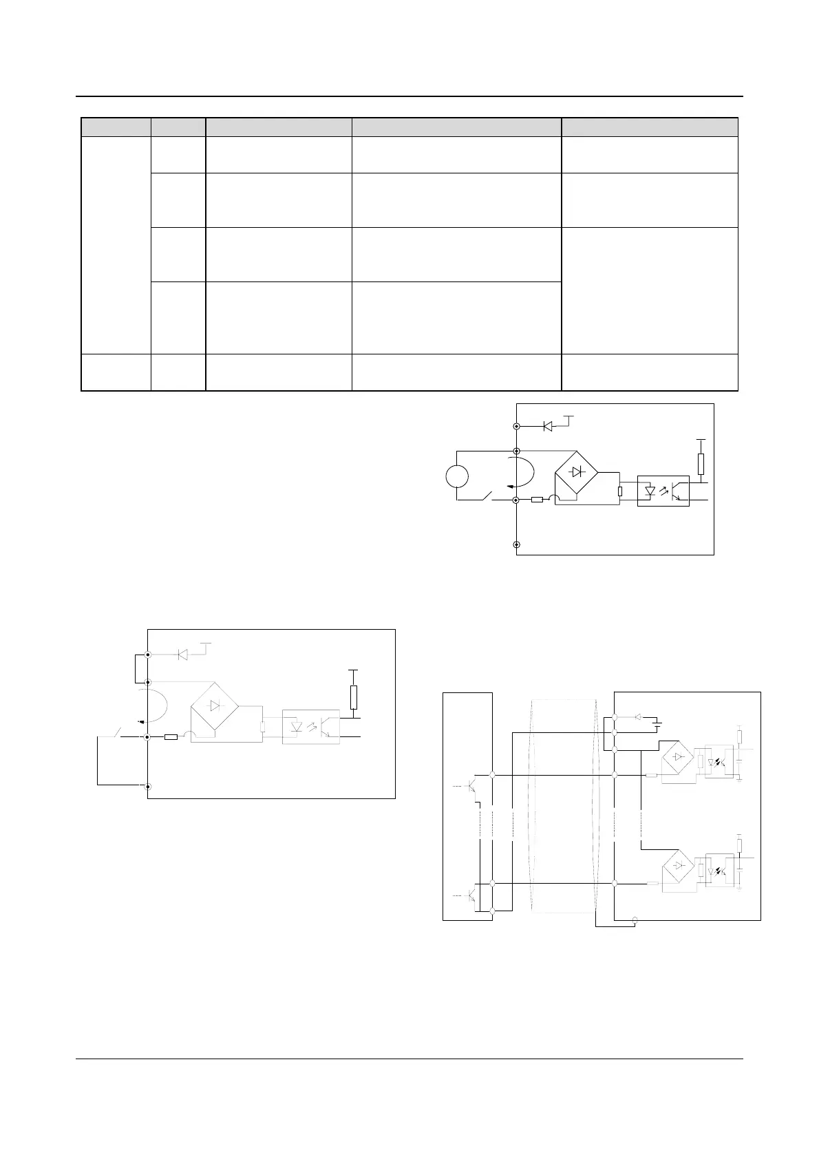
②If an external power supply is used, then use the Wire
connections shown in Fig. 3-23. (be sure to disconnect
the cable between P24 and PLC)
power
+24V
、
X1 X2 . . . X8
、
FWD
REV
PLC
EV2000
+5V
COM
P24
R
DC
+
-
K
+
-
Fig. 3-23 Using an external supply
B). Method 2 of connections
①Drive’s internal +24V power supply is used and the
external controller uses NPN transistors whose common
emitters are connected, as shown in Figure 3-24.
shielded cable's end near the drive
should be connected to the PE
COM
●
EV2000
PE
●
1
●
PLC
FWD
●
●
●
P24
COM
●
●
24V DC
D2
+
-
5V
10
●
X8
●
5V
External controller
Fig. 3-24 Method 2 of connections(a)