Chapter 5 Parameter Introductions 81
EV2000 Series Universal Variable Speed Drive User Manual
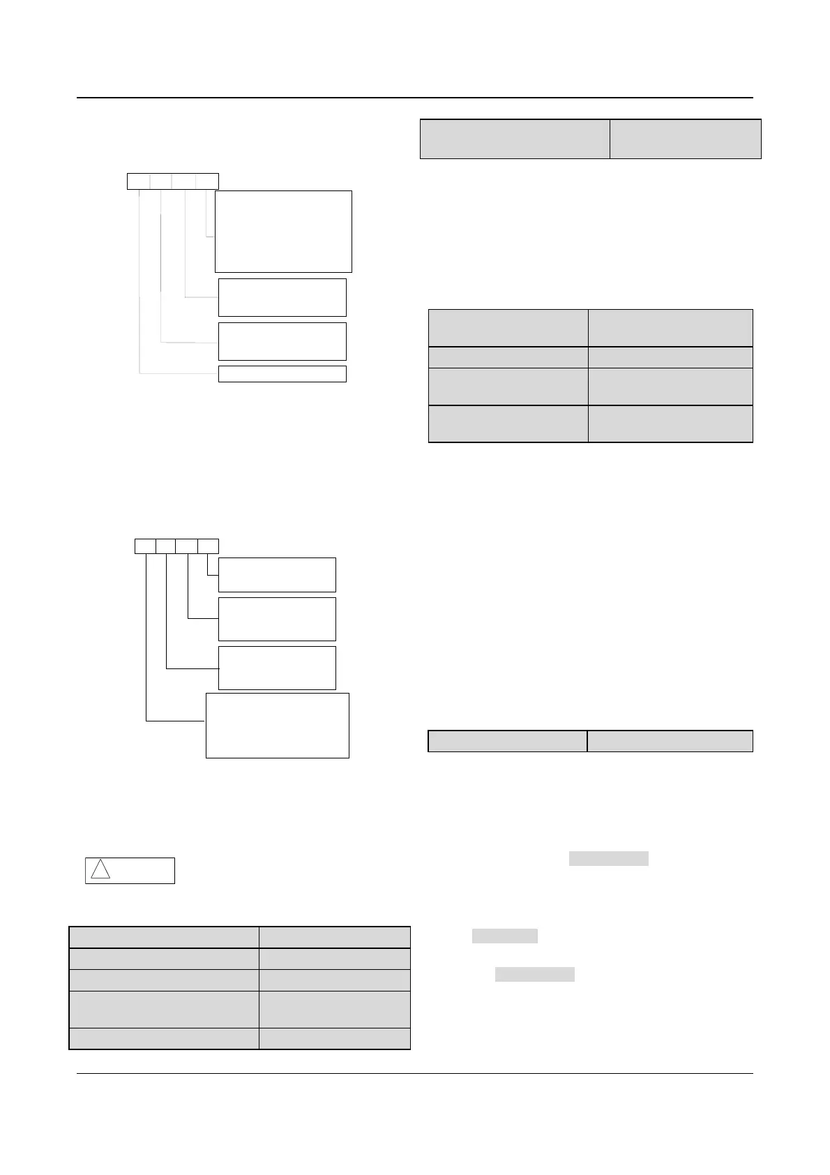
FL.12 defines the protective actions when
communication fault, contactor fault or EEPROM fault
occurs.
A
B
C
D
Action for communication fault
0: Alarm and coast to stop
1: No alarm, continue operation
2: No alarm, stop in stopping
mode (only in serial port control mode)
3: No alarm, stop in stopping
mode
( all control modes)
Action for contactor fault
0: Alarm and coast to stop
1: No alarm, continue operation
Action for EEPROM fault
0: Alarm and coast to stop
1: No alarm, continue operation
Reserved
Fig. 5-75 Protective action 1
Where,
A: thousand’s place B: Hundred’s place
C: Ten’s place D: Unit’s place
FL.13 defines the protective actions when the drive is in
under-voltage status, auto reset interval and fault
lock-up status.
A
B
C
D
Indication for under volt fault
-
0: No indication
1: Indicate the fault
Indication for auto reset fault
0: No indication
1: Indicate the fault
Fault lock -up
0: Disable
1: Enable (no fault indication)
2: Enable (indicate the fault)
Phase- failure protection
0: Input&output phase failure protect
1: No input phase failure protect
2: No output phase failure protect
3: No input&output phase failure
protect
Fig. 5-76 Protective action 2
Where,
A: Thousand’s place B: Hundred’s place
C: Ten’s place D: Unit’s place
Attention
!
Please set FL.12 and FL.13 carefully,
otherwise human injury or equipment damage may
occur.
FL.14 Type of third latest fault
Range:0~24【0】
FL.15 Type of second latest fault
Range:0~24【0】
FL.16 Type of latest fault
Range:0~24【0】
FL.17 DC Bus Voltage at last
fault
Range:0~999V【0V】
FL.18 Output current at last fault
Range:0~999.9A【0.0A】
FL.19 Frequency at last fault
Range:0.00~650.00Hz
【0.00Hz】
EV2000 has 24 types of protective alarms and it can
memorize the types of 3 latest faults (FL.14~FL.16), and
the voltage, current and frequency (FL.17~FL.19) of
latest fault.
See chapter 7 for the detailed descriptions of alarms.
5.15 Drive Parameters (Group Fn)
Fn.00 Preset operating
time
Range:0~65.535k hours【0】
Fn.01 Total operating time
Range:0~65.535k hours【0】
Fn.02 Temperature of
heatsink 1
Range: 0~100℃【0】
Fn.03 Temperature of
heatsink 2
Range: 0~100℃【0】
When the total operating time reaches the preset
operating time (Fn.00), the drive can output an indicating
signal. See F7.10~F7.12 for details.
Fn.01 records the actual operating time from first use of
the drive to the present.
Temperature of heatsink 1 is the temperature of IGBT
modules. Different IGBT modules have different
over-temperature threshold.
Temperature of heatsink 2 is the temperature of rectifier.
The drive of 45kW or below does not detect this
temperature.
Temperature display range: 0~100
℃; accuracy: 5%
5.16 Protection of Parameters (FP)
FP.00 User’s password
Range: 0000~9999【0000】
User’s password can prevent unauthorized persons from
checking and modifying the functional parameters.
Set FP.00 to 0000 if the user’s password is
unnecessary.
If the user’s password is necessary, input a 4-digit
none-zero figure, press ENTER/DATA to confirm. If not
pressing any key within 5 minutes, the password will
become effective.
Changing the password:
Press MENU/ESC, input the primary password, select
FP.00 (at this time FP.00
=0000), input new password
and press ENTER/DATA to confirm. The password will
become effective if not pressing any key within 5
minutes.
Note: