Chapter 5 Parameter Introductions 49
EV2000 Series Universal Variable Speed Drive User Manual
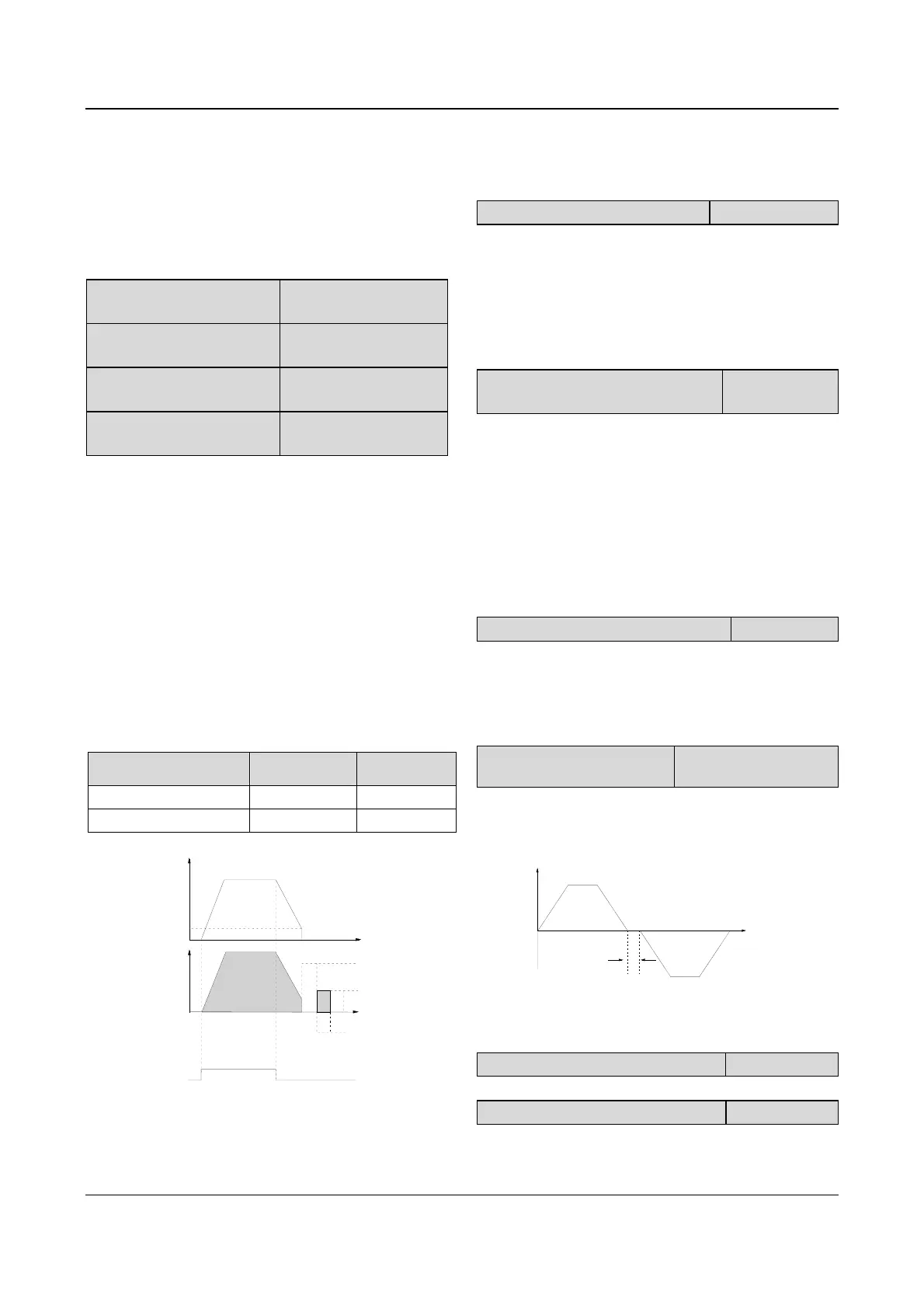
2: Dec-to-stop+DC injection braking
After receiving the STOP command, the drive reduces
its output frequency according to the Dec time and starts
DC injection braking when its output frequency reaches
the initial frequency of braking process.
Refer to the introductions of F2.09~F2.12 for the
functions of DC injection braking.
F2.09 DC injection braking
initial frequency at stop
Range:0.00~60.00Hz
【0.00Hz】
F2.10 DC injection braking
waiting time at stop
Range:0.00~10.00s
【0.00s】
F2.11 DC injection braking
current at stop
Range: dependent on
drive’s model【0.0%】
F2.12 DC injection braking
time at stop
Range: dependent on
drive’s model【0.0s】
DC injection braking waiting time at stop: The duration
from the time when operating frequency reaches the DC
injection braking initial frequency(F2.09) to the time
when the DC injection braking is applied.
The drive has no output during the waiting time. By
setting waiting time, the current overshoot in the initial
stage of braking can be reduced when the drive drives a
high power motor.
The range of DC injection braking current and time are
dependent on drive’s model, see Table 5-2.
DC injection braking current at stop is a percentage of
drive’s rated current. There is no DC injection braking
when the braking time is 0.0s.
Table 5-2 DC injection braking function
Model
Braking
current at stop
Braking time
at stop
G型 0~100.0% 0.0~30.0s
P型 0~80.0% 0.0~30.0s
Output Freq.
Initial Freq.of braking
Output
volt
(
)
RMS value
Braking
Energy
Braking time
Operating
command
Waiting time
Fig. 5-16 Dec-to-stop + DC injection braking
Note:
DC injection braking current at stop(F2.11) is a percentage
value of drive’s rated current.
F2.13 Dynamic braking
Range:0,1【0】
0: Dynamic braking is disabled
1: Dynamic braking is enabled
Note:
This parameter must be set correctly according to the actual
conditions, otherwise the control performance may be
affected.
F2.14 Ratio of working time of braking
kit to drive’s total working time
Range:0.0~
100.0%【2.0%】
This function is effective for the drive with built-in braking
resistor.
Note:
Resistance and power of the braking resistor must be taken
into consideration when setting this parameters.
5.4 Auxiliary Operating Parameters
(Group F3)
F3.00 Anti-reverse running function
Range:0. 1【0】
0: disabled
1: enabled
Note:
This function is effective in all control modes.
F3.01 Delay time of run
reverse/forward
Range:0~3600s【0.0s】
The delay time is the transition time at zero frequency
when the drive switching its running direction as shown
in Fig. 5-17 as t
1
.
Time
t
1
Output
frequency
Fig. 5-17 Delay time from reverse running to forward
running or from forward running to reverse running
F3.02~F3.04 Reserved
Reserved.
F3.05 auto energy-saving function
Range:0. 1【0】
0:disabled
1: enabled