22 Chapter 3 Installation and Wiring
EV2000 Series Universal Variable Speed Drive User Manual
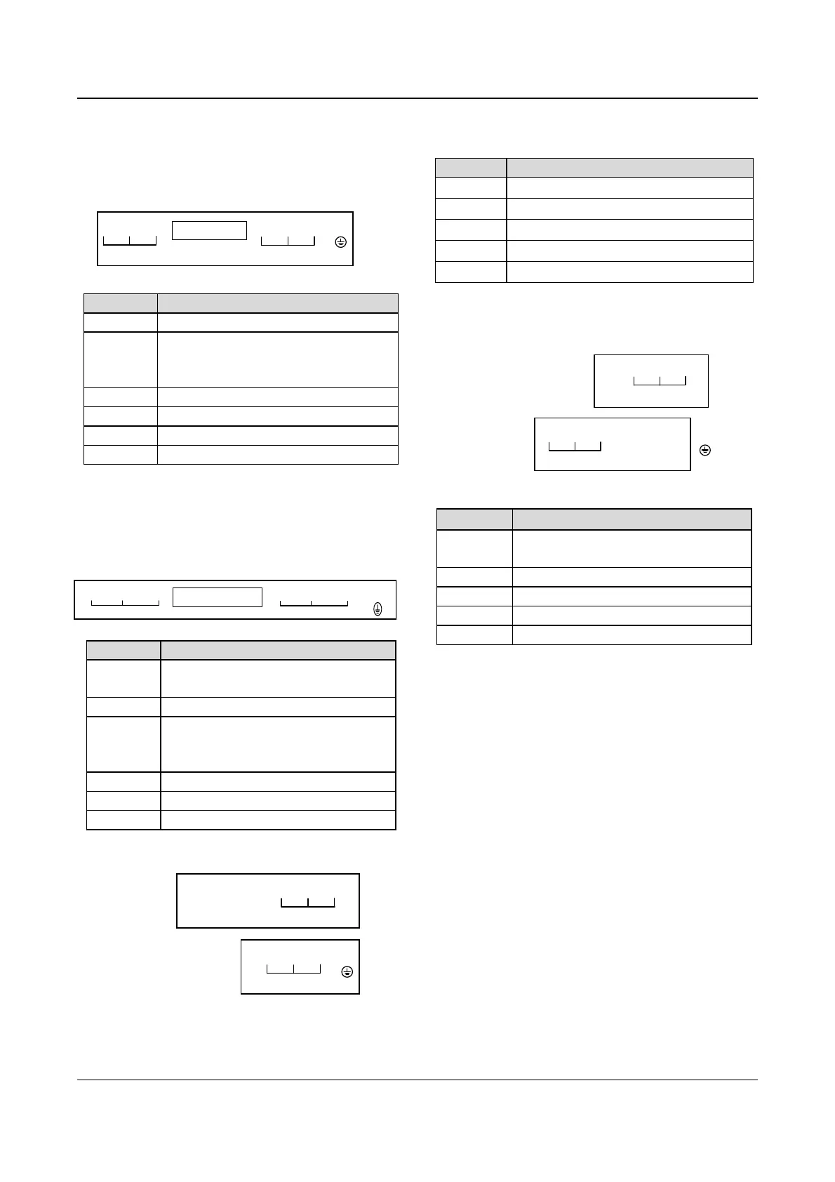
3. Input/Output Terminals in Main Circuit
1) Applicable models:
EV2000-4T0055G/0075P~EV2000-4T0150G/0185P
R S T P1 (+) PB (-) U V W PE
POWER SUPPLY MOTOR
Table 3-3 Terminals of main circuit
Terminals Function
R, S, T 3-phase 380V AC supply input terminals
P1, (+)
Reserved terminals for DC reactor,
connected with copper bar before
delivery.
(+), PB Reserved terminals for braking resistor
(-) Output terminal for DC Minus Bus
U, V, W 3-phase AC output terminals
PE Earth terminal
Notes:
Terminals PB of EV2000-4T0110G/0150P and
EV2000-4T0150G/0185P are suspended.
2) Applicable models:
EV2000-4T0185G/0220P~EV2000-4T0450G/0550P
RS T
POWER SUPPLY
P1
(+)
(-)
UVW
PE
MO T O R
P
Table 3-4 Terminals of main circuit
Terminals Function
R. S. T
3-phase 380V AC supply input
terminals
P
Positive pole of the rectifying bridge
P1, (+)
Reserved terminals for DC reactor,
connected by copper bar before
delivery
(-)
Output terminal for DC Minus Bus
U. V. W
3-phase AC output terminals
PE
Earth terminal
3) Applicable models:
EV2000-4T0550G. EV2000-4T0750P
(-) (+) P1 R S T
POWER SUPPLY
To
:
U V W PE
MOTOR
Bottom
:
Table 3-5 Terminals of main circuit
Terminal Function
R, S, T
3-phase 380V AC supply input terminals
P1, (+)
Reserved terminals for DC reactor
(-)
Output terminal for DC Minus Bus
U, V, W
3-phase AC output terminals
PE
Earth terminal
4) Applicable models:
EV2000-4T0750G~EV2000-4T2200G
EV2000-4T0900P~EV2000-4T2800P
R S T
POWER SUPPLY
To
:
U V W P1 (+) (-) PE
MOTOR
Bottom:
Table 3-6 Terminals of main circuit
Terminals Function
R. S. T
3-phase 380V AC supply input
terminals
P1. (+) Reserved terminals for DC reactor
(-)
Output terminal for DC Minus Bus
U. V. W 3-phase AC output terminals
PE Earth terminal
3.3.2 Wiring of Control Circuit
1. Terminals and jumpers of control board
Locations of terminals CN5, CN6 and CN7 and jumpers
CN10, CN14, CN16 and CN17 are shown in Fig. 3-.
Terminal functions are given in Table 3-6. Refer to table
3-7 for the functions and settings of jumpers. Wire the
terminals and set the jumpers correctly before using the
Drive. It is recommended to use cables bigger than
1mm
2
to connect to the terminals.