70 Chapter 5 Parameter Introductions
EV2000 Series Universal Variable Speed Drive User Manual
Press XX key to scroll through the parameters set in F8.02
during operation.
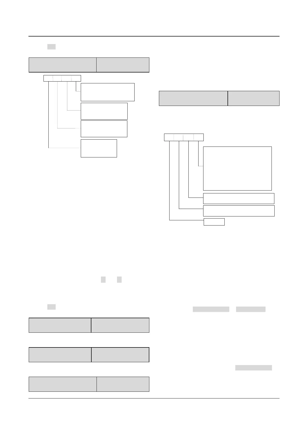
F8.03 Parameters displayed at
STOP state
Range:0000~3FFFH
【1FFH】
A
B
C
D
BIT0 : preset frequency Hz
BIT1: external counting value
BIT2: running rotating speed rpm
BIT3: preset rotating speed rpm
BIT0 : running line speed m/s
BIT1: preset line speed m/s
BIT2
:
VCI V
BIT3: CCI V
BIT0: closeloop reference %
BIT1: closeloop setting
%
BIT2: actual length
BIT3: preset length
BIT0 : terminal status
BIT1: bus voltage
BIT2: reserved
BIT3: reserved
Fig. 5-55 Stopping parameters displayed by LED
Where,
A: thousand’s place B: Hundred’s place
C: Ten’s place D: Unit’s place
F8.03 defines the parameters that can be displayed by
LED in stopping process.
If Bit is 0, the parameter will not be displayed, and if Bit
is 1, the parameter will be displayed.
For example, Bit0 decides whether to display the “preset
frequency”, if Bit0=0, the parameter will not be displayed,
if Bit0=1, the parameter will be displayed.
When setting this parameter, see Table 5-13 for
conversion of binary code and HEX value.
Note:
When the rotating speed and line speed are displayed, these
values can be revised by pressing ▲ and ▼ directly (no
need to change to frequency displaying status).
When the setting of F8.03 is 0, the preset frequency will be
displayed.
Press XX key to scroll through the parameters set by F8.03
when the drive stops.
F8.04 Rotating Speed
display coefficient
Range:0.1~999.9%
【100.0%】
F8.04 is used to correct the error of displayed rotating
speed and it has no influence on actual speed.
F8.05 Line speed display
coefficient
Range:0.1~999.9%
【1.0%】
F8.05 is used to correct the error of displayed line speed
and it has no influence on actual speed.
F8.06 Close-loop parameter
display coefficient
Range:0.1~999.9%
【100.0%】
F8.06 is used to correct error between actual physical
value (pressure or flow) and reference or feedback
values (voltage or current). It has no influence on
close-loop PI regulation.
5.10 Enhanced Functions(Group F9)
F9.00 Control mode bundled
with frequency selector
Range:000~666
【000】
F9.00 can bundle 3 control modes with 6 reference
frequency selectors, that is, if a control mode is selected,
then a frequency selector (such as panel input, analog
VCI input) will be selected automatically.
A
B
C
D
Reference selector in panel control mode
0: No bundling
1: Digital setting1 (
and
▼
)
2: Digital setting 2 ( terminal
UP/DN
)
3: Digital setting 3 (serial port )
4: VCI analog input
5: CCI analog input
6: Pulse terminal input
Reference selector in terminal control mode
~0 6 : same with above
Reference selector in serial port control mode
Reserved
▲
~0 6 : same with above
Fig. 5-56 Control mode is bundled to frequency selector
Where,
A: thousand’s place B: Hundred’s place
C: Ten’s place D: Unit’s place
The reference frequency selector is defined by F0.00,
see section 5.1 for details.
Different control modes can be bundled to one reference
frequency selector.
There are 3 methods to select control modes:
Method 1: change F0.03 “Control modes selector”;
Method 2: use PANEL/REMOTE or ENTER/DATA;
Method 3: use the terminals that can select control
modes (Functions of terminals X1~X8 should be set to
No. 28 and 29 functions.)
For example:
In order to realize remote and local control, it requires
that:
①Control modes selection: The control modes can be
selected by terminal remotely or by PANEL/REMOTE
locally;