Chapter 5 Parameter Introductions 71
EV2000 Series Universal Variable Speed Drive User Manual
②If panel control mode is used, press RUN to run the
drive and press STOP to stop the drive. The preset
frequency can be adjusted by pressing ▲ and ▼.
③If terminal control mode is used, connect FWD
terminal to run forward and connect REV terminal to run
reverse. The preset frequency is adjusted via VCI.
④Terminal control mode is enabled after the drive is
switched on.
Remote
Multi-function input
Terminal Xi
Local
Panel control
modeTerminal control
mode
Digital setting
mode 1
VCI input
PANEL/REMOTE
ENTER/DATA
Power on
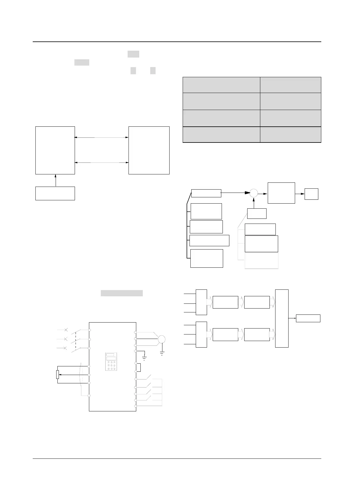
Fig. 5-57 Remote and local control
Set the parameters below to realize remote and local
control:
Set F0.03=1 to select terminal control mode and remote
control is enabled after the drive is switched on;
Set F7.00=28, F7.01=29, to select multi-function input
terminal X1 and X2 to input operating commands;
Set F7.08=1, to select 2-wire control mode 2. The drive
run forward when FWD is enabled, and run reverse
when REV is enabled;
Set F9.07 to 020 to enable PANEL/REMOTE;
If F9.00=041, then terminal control mode is bundled to
VCI analog reference, and the panel control mode is
bundled to digital reference setting 1.
EV2000
U
V
W
PE
M
R
S
T
3-phase
AC
supply
QF
PLC
COM
VRF
VCI
GND
.
.
.
.
.
REV
.
.
.
P24
FWD
4.7k
.
PE
K1
K2
.
X1
.
X2
K3
K4
Fig. 5-58 Wiring of remote and local control
Note:
The parameter is default 000, that is, the frequency selector
is not bundled with control mode.
F9.01 Auxiliary reference
frequency selector
Range: 0~12【0】
F9.02 Auxiliary analog
reference frequency coefficient
Range: 0.00~9.99
【1.00】
F9.03 Initial auxiliary digital
reference frequency
Range: 0.00~650.0Hz
【0.00Hz】
F9.04 Auxiliary digital
reference frequency control
Range: 000~111【000】
The preset frequency of EV2000 drive is the result out of
the operation on the main reference frequency and
auxiliary reference frequency. F9.01~F9.04 define the
auxiliary reference frequency selector. Fig. 5-59 shows
the process of operation.
F1
Main ref. freq.
Common
operating freq.
(F0.00=0~5)
Preset freq.
(F3.23~F3.29)
PLC operating freq.
(F4.00~F4.14)
Close-loop
operating freq.
(F5.00~F5.26)
Preset
freq.
Coefficient
adjustment
(F9.05, F9.06)
+
F2
F3 F4
Auxiliary
ref. freq.
No auxiliary
freq.(F9.01=0)
Digital setting of
auxiliary
freq.(F9.01=1~3)
Analog setting of
auxiliary ref.
freq.(F9.01=4~12)
Fig. 5-59 Preset frequency
▲▼
Serial
port
UPDN
CCI
PULSE
VCI
Analog
Digital
Aux. ref. freq.
Gain processing
F9.02
Pre-processing
Initial value and sign
of aux. ref.
F9.03 and F9.04
Setting F9.04
Setting of F1.00
Setting
of
F9.01
Pre-processing
Fig. 5-60 Auxiliary reference frequency selector
Auxiliary reference frequency is controlled by
F9.01~F9.04. F9.01 defines the auxiliary reference
frequency selector.