72 Chapter 5 Parameter Introductions
EV2000 Series Universal Variable Speed Drive User Manual
Table 5-14 Auxiliary reference frequency selector
SN Reference selector Features
0
No auxiliary reference
frequency
Zero
1
Digital setting 1, set the
reference by ▲ and ▼
Reference is set by
F9.03, the changed
frequency will be
saved in F9.03 upon
power outage.
2
Digital setting 2, set the
reference by UP/DN
3
Digital setting 3, set the
reference serial port
4 VCI analog input
Determined by
actual input analog
value, see F1.00 for
frequency curves
5 CCI analog input
6 PULSE terminal input
7 - VCI analog input
8 - CCI analog input
9 - PULSE terminal input
10 VCI-5
Determined by
actual input analog
value, see F1.00 for
frequency curves
11 CCI-5
12 PULSE-0.5×F1.03
If digital setting 3 is selected, and the frequency
reference is input via the serial port, then the auxiliary
frequency can be changed by setting F9.03 through the
host.
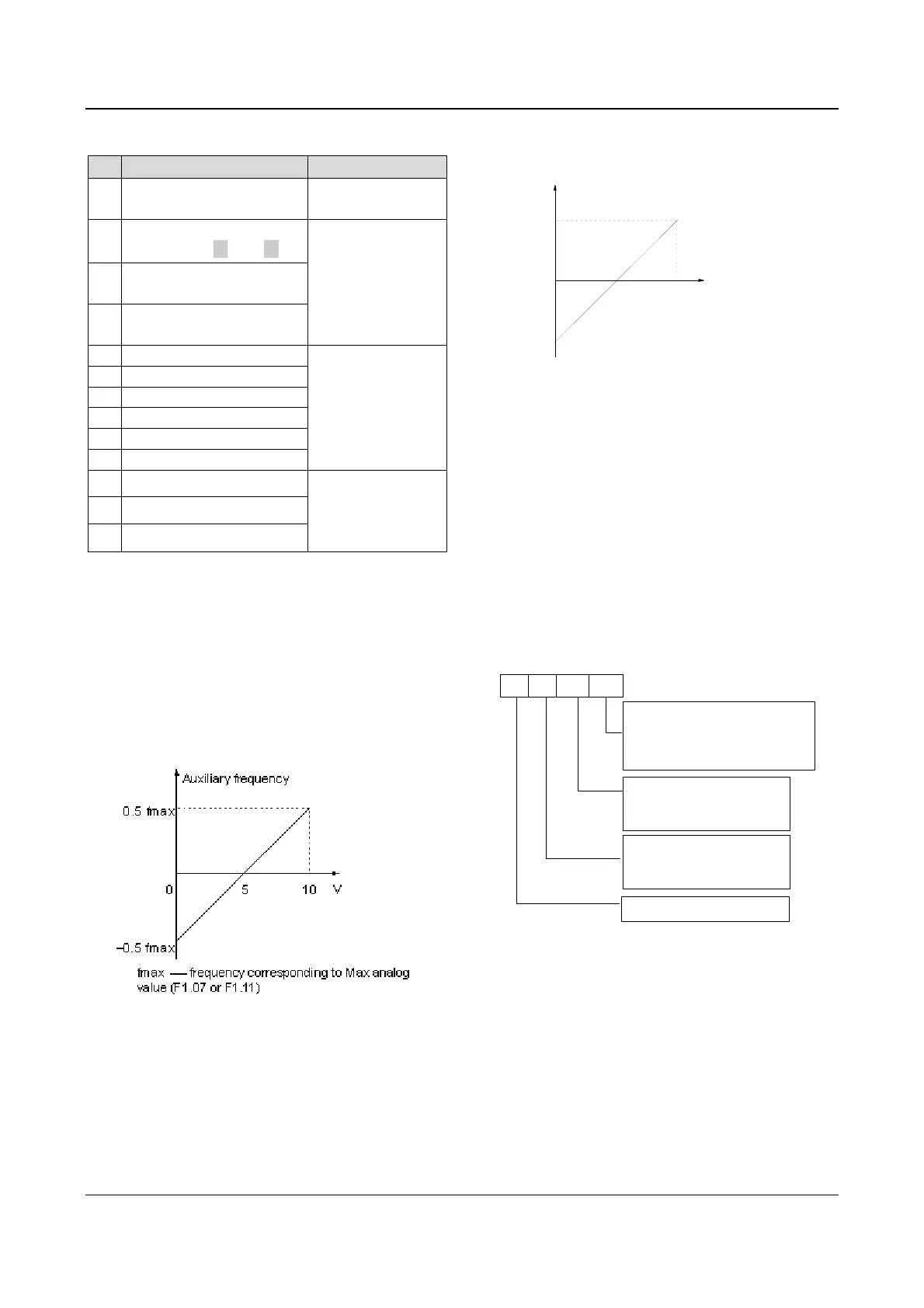
When selecting VCI-5 or CCI-5 to input auxiliary
reference frequency, the 5V analog input should be
used as a central point, from 0 to 5V, the reference
frequency drops with the increase of voltage
,while from
5 to 10V, the frequency increases with voltage. For
example, as shown in Fig. 5-61:
Fig. 5-61 VCI-5/CCI-5 as auxiliary ref. setting method
When using PULSE-0.5×F1.03 to determine auxiliary
reference frequency, one half of F1.03 (Max input pulse
frequency) is the central point. Within 0~0.5×F1.03 pulse
frequency, the reference frequency decreases with the
increase of pulse frequency; within 0.5×F1.03~F1.03, the
reference frequency increases with pulse frequency. For
example, as shown in Fig. 5-62:
0
F1.03
Pulse
Auxiliary frequency
0.5 fmax
-0.5 fmax
Pmid——1/2 *Max input pulse frequency (F1.03)
fmax——frequency corresponds to Max analog
value (F1.07 or F1.11)
Pmid
Fig. 5-62 PULSE-0.5×F1.03 as auxiliary ref. setting
method
F9.02: Coefficient of analog auxiliary reference
Only valid when F9.01=4~12. First, use F9.02 to
calculate the gain and then calculate the auxiliary
reference frequency by the frequency curve defined by
F1.00.
F9.03: initial value of digital reference frequency
Only valid when F9.01=1~3. F9.03 defines the initial
values of digital reference frequency when F9.01=1~3.
F9.04: digital auxiliary reference frequency control
Only valid when F9.01=1~3, as shown in Fig.5-63.
A
B
C
D
Save
0: Save ref. Freq. upon power outage
1: Not save ref. F
req. upon power
outage
Stopping freq.
0: Hold ref. Freq. at stop
1: Clear ref. Freq. at stop
Sign of auxi. ref. Freq.
0: +, main ref+ auxi. ref. Freq.
1:
-
, main ref
-
auxi. ref. Freq.
Reserved
Fig. 5-63 Digital auxiliary reference frequency control
Where,
A: thousand’s place B: Hundred’s place
C: Ten’s place D: Unit’s place
Unit’s place: parameter-saving function at power off
0: Save the auxiliary reference frequency at power off
The auxiliary frequency will be stored in F9.03 at power
off. The sign of auxiliary reference frequency is saved in
F9.04.
1: not save the auxiliary frequency at power off