Chapter 3 Installation and Wiring 23
EV2000 Series Universal Variable Speed Drive User Manual
DSP
CN1 CN2
CN3
CN4
CN9
CN16
CN17
CN14
CN10
CN5
CN6
CN7
mA
V
mA
V
232
485
I
V
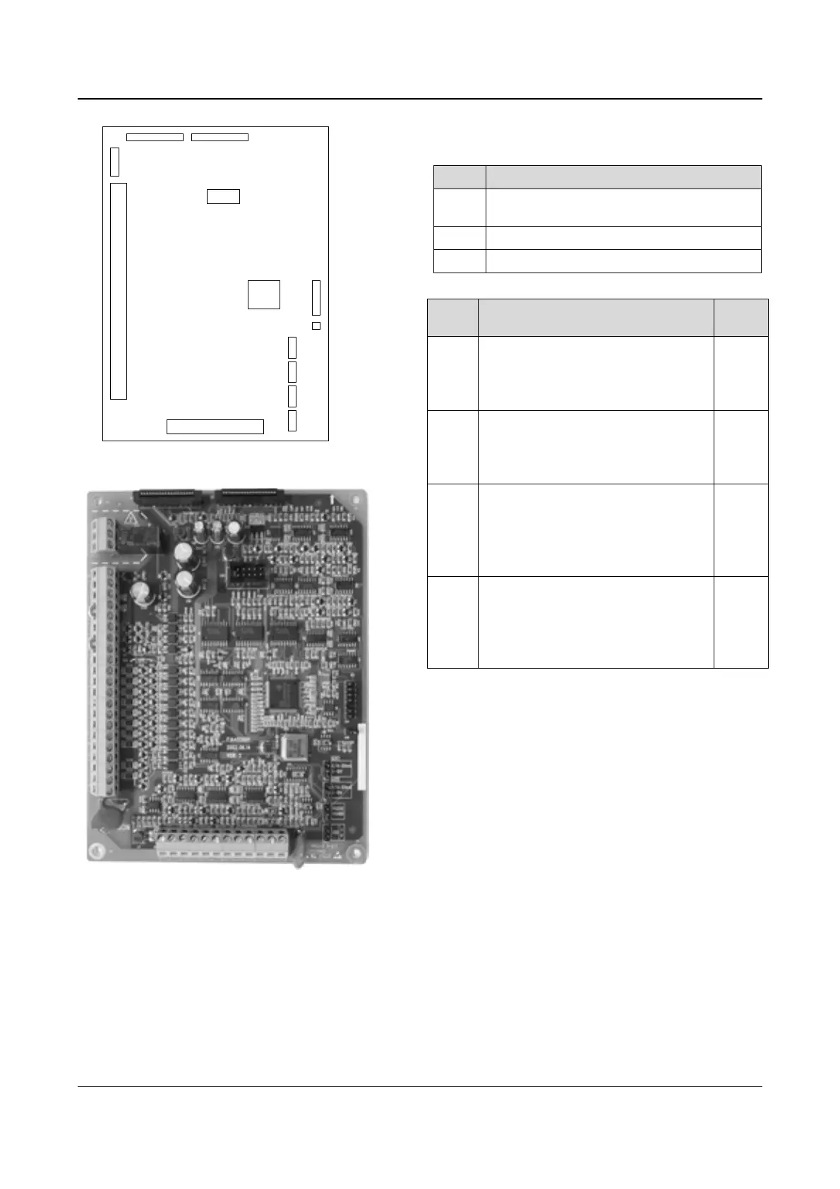
Fig. 3-12 Locations of jumpers on the control board
Table 3-7 Functions of terminals provided to users
SN Function
CN5
Analog input and output terminal, RS232 and
RSRS485 communication port
CN6 Digital input/output terminal
CN7 Relay output terminal
Table 3-8 Functions of jumpers provided to users
SN Function and settings
Factory
settings
CN10
Used for selecting CCI current/voltage
input
I: 0/4~20mA current signal,
V: 0~10V voltage signal
0~10V
CN14
Used for selecting communication
ports (RS232 or RS485)
RS232: Select RS232 port,
RS485: Select RSRS485 port
RS485
CN16
Used for selecting the output signal
(current or voltage) of analog output
terminal AO1;
0/4~20mA: AO1 output current signal;
0~10V: A01 output voltage signal
0~10V
CN17
Used for selecting the output signal
(current or voltage) of analog output
terminal AO2;
0/4~20mA: AO2 output current signal;
0~10V: AO2 output voltage signal
0~10V
Fig. 3-13 Control board