24 Chapter 3 Installation and Wiring
EV2000 Series Universal Variable Speed Drive User Manual
2. Wire connections of terminals on control board
1) Terminal CN5 on control board
Arrangements of terminals of CN5:
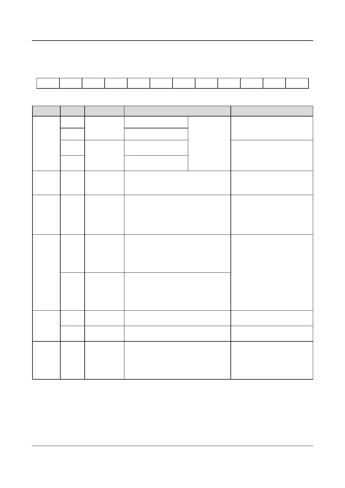
VRF VCI CCI GND AO1 AO2 GND TXD RXD 485+ 485- PE
Functions of terminals of CN5 are given in Table 3-.
Table 3-9 Functions of the terminals
Category Terminals Name Function Specification
Communication
RS485+
RS485
communication
port
RS485 +
RS232/RS485
can be selected
by jumper CN14,
RS485 mode is
the default
mode.
Standard RS-485 communication
port, please use twisted-pair cable
or shielded cable.
RS485- RS485 -
TXD
RS232
communication
port
Transmitting pin
(Reference ground: GND)
Standard RS232 communication
port, 3-wire connection (only use
TXD, RXD and GND).
Maximum distance: 15m
RXD
Receiving pin (reference
ground: GND)
Analog
input
VCI
Analog input
VCI
Be able to accept analog voltage input
(Reference ground: GND)
Input voltage range:0~10V
(input resistance:100kΩ)
Resolution: 1/2000
Analog
input
CCI
Analog input
CCI
Be able to accept analog voltage/current
input. Jumper CN10 can select voltage or
current input mode, Voltage input mode is
the default mode.(reference ground: GND)
Input voltage range:0~10V(input
resistance:100kΩ)
Input current range:0~20mA
(input resistance:500Ω)
Resolution: 1/2000
Analog
output
AO1 Analog output 1
Be able to output analog voltage/current
(total 12 kinds of signals). Jumper CN16 can
select voltage or current input mode, Voltage
input mode is the default mode. Refer to
F7.26 for details. (reference ground: GND)
Output current range: 0/4~20mA
Output voltage range:0/2~10V
AO2 Analog output 2
Be able to output analog voltage/current
(total 12 kinds of signals). Jumper CN17 can
select voltage or current input mode, Voltage
input mode is the default mode. Refer to
F7.27 for details.(reference ground: GND)
Power
supply
VRF
+10V power
supply
Provide +10V power supply Maximum output current is 50mA
GND
GND of +10V
power supply
Reference ground of analog signal and 10V
power supply
Isolated with COM and CME
Shielding
layer
PE
GND of
shielding layer
Terminal used for the earthing the shielding
layer. The shielding layers of analog signal
cable, RS485 communication cable and
motor cable can be connected to the
terminal.
Connected to PE inside the drive.
1. Wiring analog input terminal
①VCI can accept analog voltage signal input and wiring is shown below:
 Loading...


