Chapter 3 Installation and Wiring 25
EV2000 Series Universal Variable Speed Drive User Manual
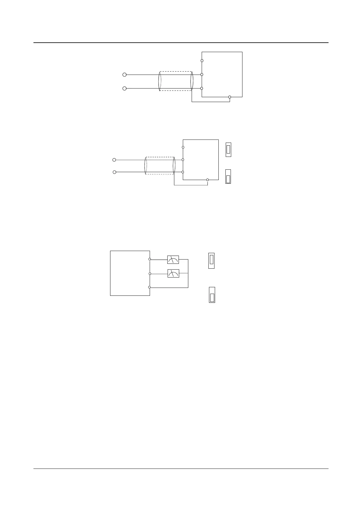
Nearer shielding wire's end is
connected to PE
VRF(+10V)
VCI
GND
●
PE
~0+
10V
EV2000
●
●
●
Fig. 3-14 Wiring terminal VCI
②CCI can accept analog signal input and the jumper can be used to select voltage input (0~10V) and current input
(0/4~20mA). The wiring is shown below:
···
CCI current
I
V
···
CCI voltage
I
V
CN10
Nearer shielding wire's
end that is connected to
the PE
VRF(+10V)
CCI
GND
PE
~
0+10V
~or 0/4
20mA
EV2000
●
●
●
●
Fig. 3-15 Wiring CCI
2. Wiring connections analog output terminal
If the analog output terminals AO1 and AO2 are connected to analog meters, then various kinds of physical values can
be indicated. The jumper can select current output (0/4~20mA) and voltage output(0/2~10V). The wiring is shown in
Fig.3-16..
AO1
AO2
GND
···
Analog current
output
0/4-20mA
0-10V
Analog
meter
···
Anlog voltage
output
0/4-20mA
0-10V
:
;:
AO1CN16AO2
CN17
EV2000
●
●
●
Fig. 3-16 Wiring analog output terminal
Notes:
(1) When using analog input, a common mode inductor can be installed between VCI and GND or CCI and GND.
(2) Analog input and output signals are easily disturbed by noise, so shielded cables must be used to transmit these signals and
the cable length should be as short as possible.
3. Wiring of Serial Communication Port
Wire connections of serial communication port.
EV2000 drive provides two kinds of serial ports: RS232 and RS485 which can be selected by Jumper CN14.
Wire as following figures show, and a “single-master single slave” system or a “single-master multi-slaves” system can
be formed. The drives in the network can be monitored and controlled remotely and automatically in real time by using a
PC or PLC controller. Thus more complicated operation control can be realized (e.g. Unlimited multi-step PLC
operation).
① The drive connects to the host via its RS232 port:
 Loading...


