48 Chapter 5 Parameter Introductions
EV2000 Series Universal Variable Speed Drive User Manual
Notes:
Starting frequency is not restricted by the lower limit of
frequency.
F2.03 DC injection braking
current at start
Range: dependent on
drive’s model【0.0%】
F2.04 DC injection braking
time at start
Range: dependent on
drive’s model【0.0s】
F2.03 and F2.04 are only active when F2.00 is set to 1
(starting mode 1 is selected), as shown in Fig. 5-13.
The range of DC injection braking current and time are
dependent on the drive’s model, see Table 5-1.
DC injection braking current at start is a percentage
value of drive’s rated current. There is no DC injection
braking when the braking time is 0.0s.
Table 5-1 DC injection braking function
Model
The range
of current
The range of
time
G型 0~100.0% 0.0~30.0s
P型 0~80.0% 0.0~30.0s
Output
frequency
Output
voltage
(
effective
)
value
Braking
energy
DC
injection
braking time
Running
command
Time
Time
Fig. 5-13 Starting mode 1
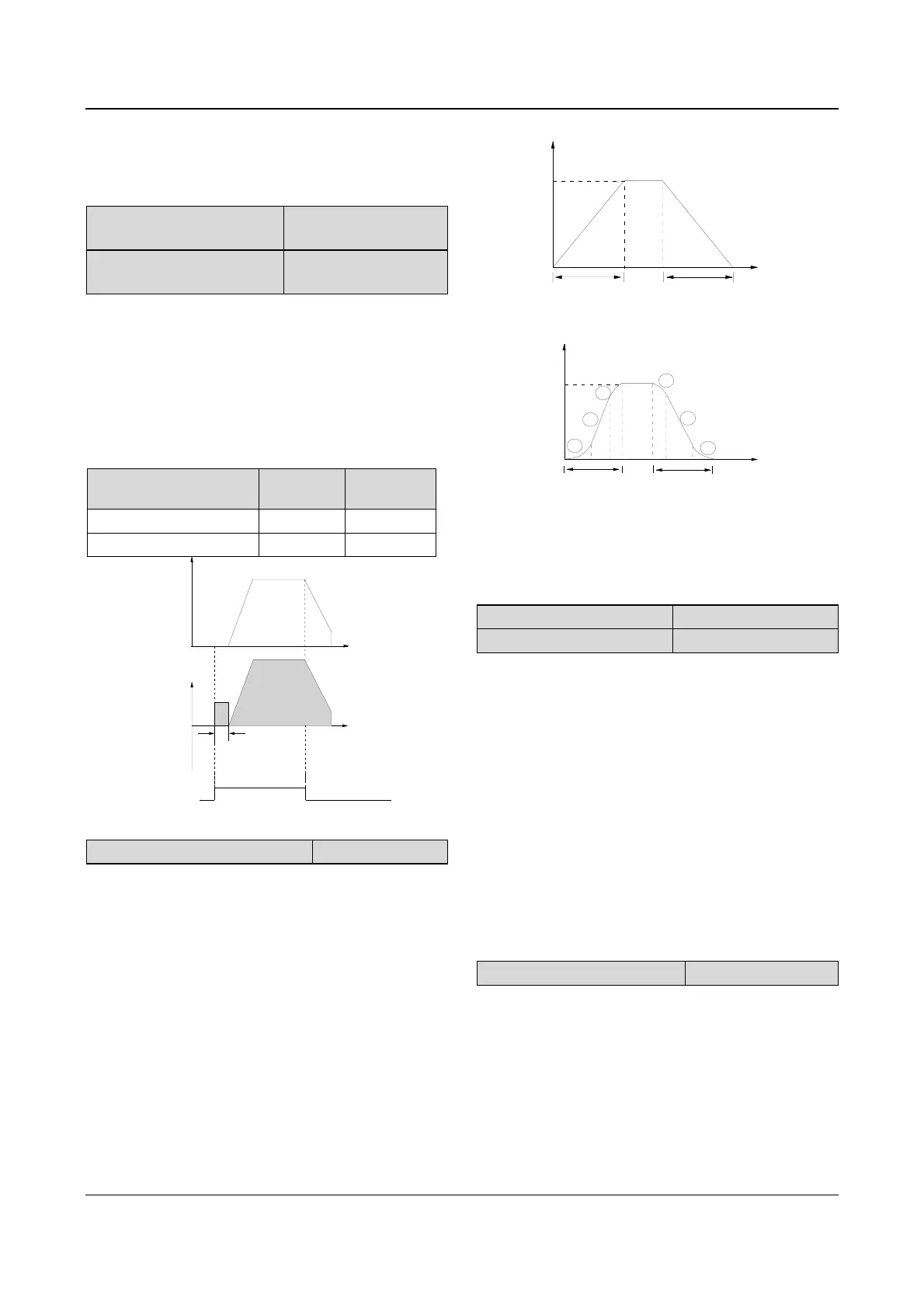
F2.05 Acc/Dec mode
Range:0. 1. 2【0】
0: Linear Acc/Dec mode
Output frequency increases or decreases according to a
constant rate, as shown in Fig. 5-14.
1: S ramp Acc/Dec
Output frequency increases or decreases according to a
S-shape curve, as shown in Fig. 5-15.
2: Acc/Dec mode with current limiting function
The drive can maintain its output current below the
current limiting threshold (see FL.07) automatically and
complete the Acc or Dec process according to the load
condition.
Frequency
Time
f
max
t
1
t
2
Fig. 5-14 Linear Acc/Dec
1
2
3
3
2
1
t
1
t
2
f
max
Frequency
Time
Fig. 5-15 S-ramp Acc/Dec
Note:
In auto Acc/Dec mode, settings of F0.10, F0.11 and
F3.17~F3.22 are invalid.
F2.06 Starting time of S ramp
Range:10~50%【20.0%】
F2.07 Rising time of S ramp
Range:10~80%【60.0%】
F2.06 and F2.07 are only active when the Acc/Dec
mode is S-ramp Acc/Dec mode(F2.05=1), and
F2.06+F2.07
≤90%.
Starting process of S-shape curve is shown in Fig. 5-15
as “
①” , where the change rate of output frequency
increases from 0;
Rising process of S-shape curve is shown in Fig. 5-15
as “
②”, where the output frequency’s changing rate is
constant;
Ending process of S-shape curve is shown in Fig. 5-15
as “
③”, where the changing rate of output frequency
decreases to 0;
S-ramp Acc/Dec mode is suitable for the conveying load
such as elevator and conveying belt.
F2.08 Stopping mode
Range:0. 1. 2【0】
0: Dec-to-stop
After receiving the stopping command, the drive reduces
its output frequency according to the Dec time, and
stops when the frequency decreases to 0.
1: Coast-to-stop
After receiving the stopping command, the drive stops
outputting power immediately and the motor stops under
the effects of mechanical inertia.