50 Chapter 5 Parameter Introductions
EV2000 Series Universal Variable Speed Drive User Manual
When the motor operates without load or with light load,
the drive can adjust its output voltage by detecting the
load current to achieve the energy-saving effects.
Note:
This function is especially useful for the fan & pump loads.
F3.06 AVR function
Range:0. 1. 2【2】
0:disabled
1: enabled all the time
2: disabled in Dec process
AVR means automatic voltage regulation.
The function can regulate the output voltage and make it
constant. Therefore, generally AVR function should be
enabled, especially when the input voltage is higher than
the rated voltage.
In Dec-to-stop process, if AVR function is disabled, the
Dec time is short but the operating current is big. If AVR
function is enabled all the time, the motor decelerates
steadily, the operating current is small but the Dec time
is prolonged.
F3.07 Gain of slip
compensation
Range:0.0~300.0%【100.0%】
F3.08 Limit of slip
compensation
Range:0.0~250.0%【200.0%】
F3.09 Compensation
time constant
Range:0.1~25.0s【2.0s】
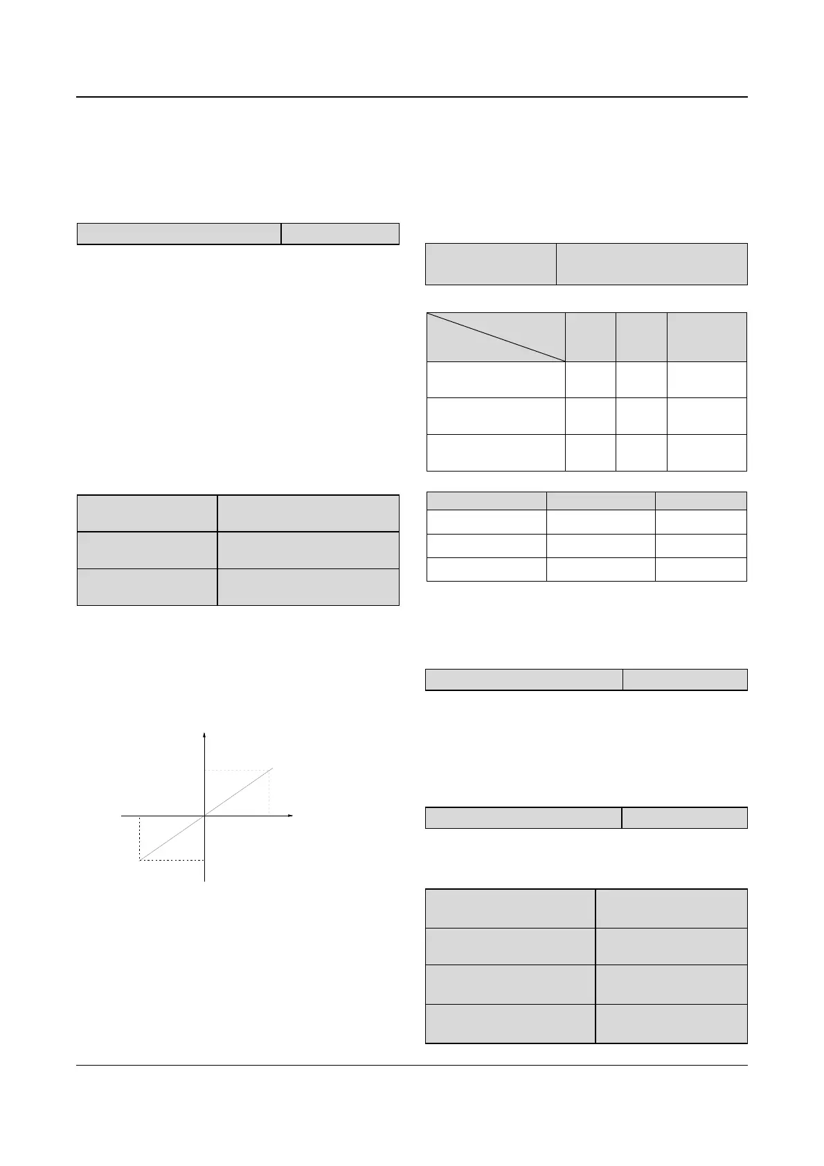
The motor’s slip changes with the load torque, which
results in the variance of motor speed. The drive’s
output frequency can be adjusted automatically through
slip compensation according to the load torque.
Therefore the change of speed due to the load change
is reduced as shown in Fig. 5-18.
100%
Motor's
load
Slip
Positive slip
compensation
-100%
Negative slip
compensation
Fig. 5-18 Auto slip compensation
Motoring status: Increase the gain of slip compensation
gradually when the actual speed is lower than the
reference speed (F3.07).
Regenerating status: Increase the gain of slip
compensation gradually when the actual speed is higher
than the reference speed (F3.07).
Range of slip compensation: limit of slip
compensation(F3.08)
× rated slip(FH.08)
Note:
The value of automatically compensated slip is dependent
on the motor’s rated slip, therefore the motor’s rated slip
must be set correctly (FH.08).
F3.10 Carrier wave
frequency
Range:0.7~15.0kHz【depend on
drive model】
Table 5-3 Drive’s type and carrier wave frequency (CWF)
CWF
Type
Highest
(kHz)
Lowest
(kHz)
Factory
setting (kHz)
Type G:5.5kW~45kW
Type P:7.5kW~55kW
15 3 8
Type G:55kW~90kW
Type P:75kW~110kW
10 1 3
Type G:110kW~220kW
Type P:132kW~280kW
6 0.7 2
Table 5-4 CWF characteristics
CWF Decrease Increase
Motor’s noise
↑ ↓
Leakage current
↓ ↑
Disturbance
↓ ↑
Notes:
In order to achieve better control performances, the ratio of
carrier frequency to the maximum operating frequency of
the drive should not be less than 36.
F3.11 Auto adjusting of CWF
Range:0. 1【1】
0: disabled
1: enabled
When this function is enabled, the drive can adjust the
CWF automatically according to the internal temperature
of the drive. At this time, the drive’s actual Max CWF is
restricted by F3.10.
F3.12 Motor tone adjustment
Range:0~10【0】
F3.12 can be used to adjust the motor’s tone, and is
only effective for the CWF below 6kHz.
If this parameter is set to 0, the function is disabled.
F3.13 Jog operating
frequency
Range:0.10~50.00Hz
【5.00Hz】
F3.14 Interval of Jog
operation
Range:0.0~100.0s【0.0s】
F3.15 Acc time of Jog
operation
Range:0.1~60.0s
【6.0s/20.0s】
F3.16 Dec time of Jog
operation
Range:0.1~60.0s
【6.0s/20.0s】
 Loading...


