Chapter 5 Parameter Introductions 51
EV2000 Series Universal Variable Speed Drive User Manual
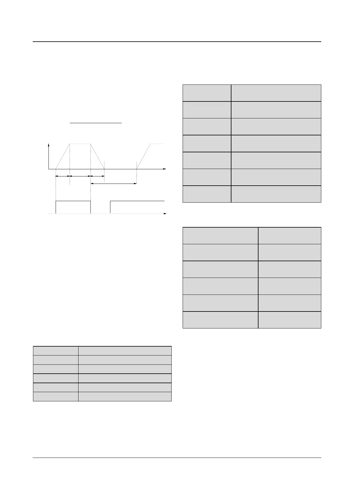
F3.13~F3.16 define the relevant parameters of Jog
operation.
As shown in Fig. 5-19, t
1
and t
3
are the actual Acc time
and Dec time respectively. t
2
is the Jog operating time; t
4
is the interval of Jog operation(F3.14); f
1
is the Jog
operating frequency(F3.13).
Actual Acc time t
1
can be determined by the following
formula, so does the actual Dec time t
3
of jog operation.
t
1
=
F3.13×F3.15
F0.05
Jog command Jog command
f
1
t
1
t
3
t
2
t
4
Time
Frequency
Time
Fig. 5-19 Jog operating parameters
Interval of Jog operation (F3.14) is the interval from the
time when the last Jog operation command is ended to
the time when the next Jog operation command is
executed.
The jog command sent during the interval will not be
executed. If this command exists until the end of the
interval, it will be executed.
Note:
1. In Jog operation process, the drive starts according to
starting mode 0 and stops according to stopping mode 0.
The unit of Acc/Dec time is second.
2. Jog operation can be controlled by panel, terminals and
serial port.
F3.17 Acc time 2
Range: 0.1~3600s(min) 【6.0s/20.0s】
F3.18 Dec time 2
Range: 0.1~3600s(min) 【6.0s/20.0s】
F3.19 Acc time 3
Range: 0.1~3600s(min) 【6.0s/20.0s】
F3.20 Dec time 3
Range: 0.1~3600s(min) 【6.0s/20.0s】
F3.21 Acc time 4
Range: 0.1~3600s(min) 【6.0s/20.0s】
F3.22 Dec time 4
Range: 0.1~3600s(min) 【6.0s/20.0s】
Three kinds of Acc/Dec time can be defined, and the
drive’s Acc/Dec time 1~4 can be selected by different
combinations of control terminals, refer to the
introductions of F7.00~F7.07 for the definitions of
terminals used to select Acc/Dec time.
Note:
1. Acc/Dec time 1 is defined in F0.10 and F0.11.
2. For the drive of 30kW or above, its factory setting of
Acc/Dec time is 20.0s.
F3.23 Preset
frequency 1
Range: Lower limit of frequency
~upper limit of frequency【 5.00Hz】
F3.24 Preset
frequency 2
Range: Lower limit of frequency
~upper limit of frequency【10.00Hz】
F3.25 Preset
frequency 3
Range: Lower limit of frequency
~upper limit of frequency【20.00Hz】
F3.26 Preset
frequency 4
Range: Lower limit of frequency
~upper limit of frequency【30.00Hz】
F3.27 Preset
frequency 5
Range: Lower limit of frequency
~upper limit of frequency【40.00Hz】
F3.28 Preset
frequency 6
Range: Lower limit of frequency
~upper limit of frequency【45.00Hz】
F3.29 Preset
frequency 7
Range: Lower limit of frequency
~upper limit of frequency【50.00Hz】
These frequencies will be used in simple PLC operation
and multi-step speed operation, refer to the introductions
of F7.00~F7.07 and group F4 parameters.
F3.30 Skip frequency 1
Range:0.00~650.00Hz
【0.00Hz】
F3.31 Range of skip
frequency 1
Range:0.00~30.00Hz
【0.00Hz】
F3.32 Skip frequency 2
Range:0.00~650.00Hz
【0.00Hz】
F3.33 Range of skip
frequency 2
Range:0.00~30.00Hz
【0.00Hz】
F3.34 Skip frequency 3
Range:0.00~650.00Hz
【0.00Hz】
F3.35 Range of skip
frequency 3
Range:0.00~30.00Hz
【0.00Hz】
F3.30~F3.35 define the output frequency that will cause
resonant with the load, which should be avoided.
Therefore, the drive will skip the above frequency as
shown in Fig. 5-2020. Up to 3 skip frequencies can be
set.
 Loading...


