56 Chapter 5 Parameter Introductions
EV2000 Series Universal Variable Speed Drive User Manual
In the above Fig., KP: proportional gain; Ki: integral gain
In Fig. 5-31, refer to F5.01~F5.15 for the definitions of
close-loop reference, feedback, error limit and
proportional and Integral parameters.
There are two features of internal PI of EV2000:
The relationship between reference and feedback can
be defined by F5.08~F5.11.
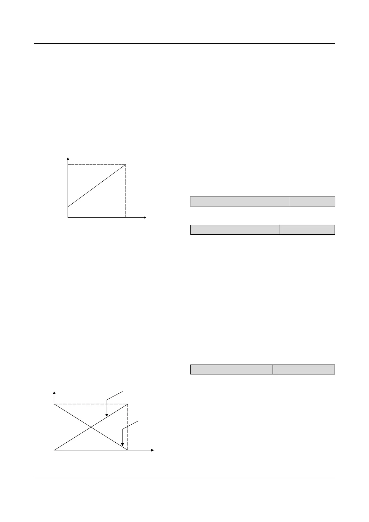
For example: In Fig. 5-29, if the reference is analog
signal of 0~10V, the controlled value is 0~1MP, and the
signal of water-level sensor is 4~20mA, then the
relationship between reference and feedback is shown
in Fig. 5-32.
10V
0
Reference
4mA
20mA
Feedback
Fig. 5-32 Reference and feedback
The reference value is a 0~10V signal (10V corresponds
to 100%); and the feedback value is 4Ma~20mA (20mA
corresponds to 100%).
In Fig 5-31, “reference regulation” and “feedback
regulation” mean that the reference value and feedback
value are converted from current or voltage value to
percentage values, so that feedback value can be added
to or subtracted from the reference value.
Close-loop reference is selected via F5.16 to satisfy
different application requirements.
If the motor’s speed is required to increases with the
reference speed, this kind of control characteristic is
called positive characteristic. If the motor speed is
required to decrease when the reference value
increases, this control characteristic is called negative
characteristic.
Please refer to Fig. 5-33 and F5.16.
Close loop
reference
Speed
Positive
Negative
Fig. 5-33 Close-loop control characteristic
After the control type is determined, follow the
procedures below to set close loop parameters.
Determine the close-loop reference and feedback
channel (F5.01 and F5.02);
The relationship between close-loop reference and
feedback value (F5.08~F5.11) should be defined for
close-loop control;
For speed close-loop, the close-loop speed reference
and the number of revolutions of PG (F5.06~F5.07)
need to be determined;
Determine the close-loop regulation characteristic, i.e.
whether the motor speed increase with the reference.
Please see F5.16.
Set up the integral regulation function and close-loop
frequency presetting function (F5.17~F5.19);
Adjust the close-loop filtering time, sampling cycle, error
limit and gain(F5.12~F5.15).
F5.00 Close-loop control function
Range:0. 1【0】
0: disabled
1: enabled
F5.01 Reference selector
Range:0. 1. 2【1】
0: digital input
Take the value of F5.05 (when the setting is analog
close-loop, F5.02
=0~5);
Take the value of F5.06 (when the setting is pulse
close-loop, F5.02
=6).
1: VCI analog voltage input(0~10V)
2: CCI analog input
Analog input range:0~10V(Jumper CN10 is placed at
side V), or 0~20mA(Jumper CN10 is placed at side I).
Note:
Use pulse feedback to control the speed. If the reference is
analog signal, then 0~10V (4~20mA) reference corresponds
to synchronous speed n
0
(n
0
=120fmax/P).
F5.02 Feedback selector
Range:0~6【1】
0: VCI 0~10V analog voltage input
1: CCI analog input
2: VCI + CCI
3: VCI-CCI
4: Min {VCI,CCI}
5: Max {VCI,CCI}
Settings of jumper CCI are the same with the above.
When current input is selected, the signal will be
converted into voltage signal by the formula:
Voltage value = current value (mA)/2;