8 Chapter 3 Electrical Installation
EV3200 Door Control Inverter User Manual
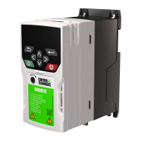
3.2 Control Terminals
A amplified view
X2P24 ACOM B X1 COMX4X3 X5 CDOD
A
EV3200
Figure 3-3 Control terminals
Table 3-4 Function description of control terminals
Terminal Terminal function Specifications
P24, COM
User terminal 24V power supply (COM being the
reference earth)
+24V ± 15%, max output current: 200mA, with output
shortcircuit protection function
A, B AB pulse input terminal of incremental PG
Meeting the input requirements of pulse signal with frequency
below 35kHz
X1 ~ X5
Multi-function input terminals (functions programmable,
COM being the reference earth), or Z pulse input
terminal of incremental PG
OD OD command input terminal
CD CD command input terminal
Terminal command valid when shorted with COM
Note
If the control cables are multi-core cables, it is recommended that the sectional area of a single strand of the control cables be 0.5mm
2
. If
the control cables are single-core cables, the cable sectional area should be greater than 1.0mm
2
.
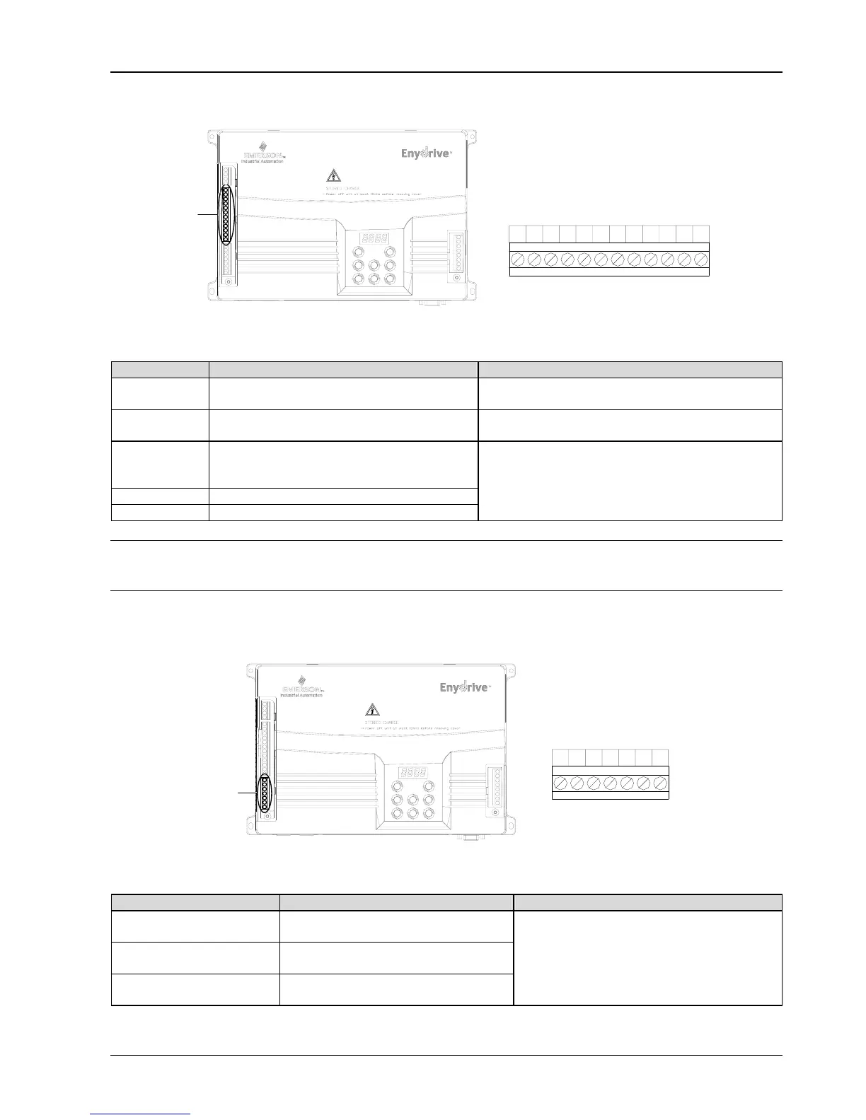
3.3 User Relay Output Terminals
A
EV3200
A amplified view
PA2PA1 PC1 PC3PA3PC2 PB3
Figure 3-4 User relay output terminals
Table 3-5 Function description of user relay output terminals
Terminal Terminal function Specifications
PA1, PC1
When F9.22 is 0: normally closed contact output
When F9.22 is 1: normally open contact output
PA2, PC2
When F9.22 is 0: normally closed contact output
When F9.22 is 1: normally open contact output
PA3, PB3, PC3
PA3, PB3: Normally closed contact output
PA3, PC3: Normally open contact output
Contact rating
AC: 250V/1A (cosΦ=0.4), 250V/2A (cosΦ=1)
DC: 30V/1A