Chapter 7 Application Guidance 39
EV3200 Door Control Inverter User Manual
Table 7-1 Motor parameters setting table
Parameter Name Setting Remark
F0.01 Control mode 0
F0.02 Control command selection 0
F0.04 Max. output frequency 50Hz
F4.00 PG type 0
F4.01 Pulse number per revolution 200
F4.02 PG direction 0
F6.00 Motor type selection 0
F6.01 Motor rated power *
F6.02 Motor rated voltage *
F6.03 Motor rated current *
F6.05 Motor rated frequency *
F6.06 Motor rated spinning speed *
F6.07 Motor tuning 0
Parameters in this table are factory settings, adjust the OD
parameters according to the actual OD operating conditions
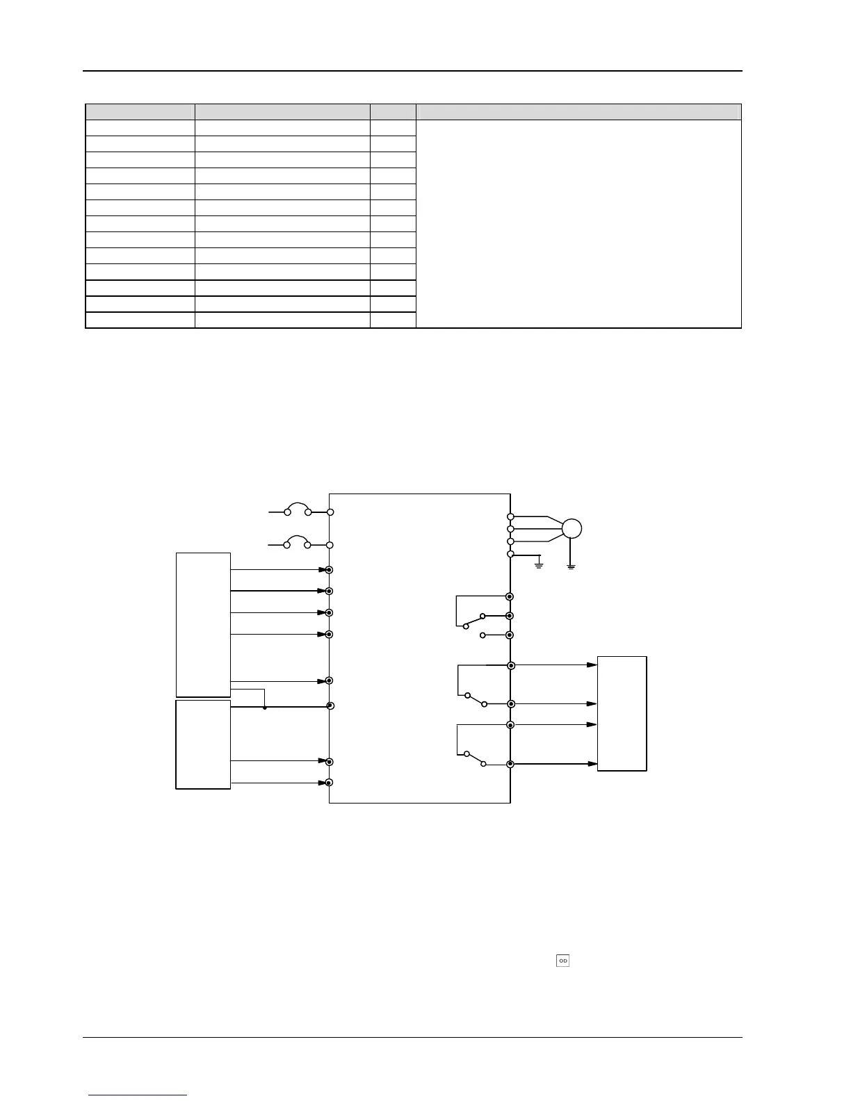
7.2 Speed Control
7.2.1 System Wiring Diagram
In speed control, speed decrease contacts are used to decrease the speed, and the position limiting signal is used to judge
whether the door is opened or closed completely. System wiring diagram for speed control 1 is shown in Figure 7-2.
L
N
Single phase
power supply
50/60Hz
M
X1
CD
U
V
W
PE
MCCB
Fault relay
OD
OD command input
CD command input
Complete OD
relay output
OD speed
decrease NO input
OD position
limiting NO input
light curtain or safety
edge signal NO input
COM
EV3200 inverter
PB3
PC3
PA3
PC2
PA1
PC1
PA2
X2
X3
X4
X5
CD speed
CD position
limiting NO input
Elevator door mechanical system
Control system
Complete CD
relay output
Control system
decrease NO input
Figure 7-2 System wiring diagram for speed control
7.2.2 Testing Procedures
1. Wiring according to Figure 7-2.
2. Switch on the inverter, set F9.18 to 2, load defaults. Refer to
4.1 Operation for parameter setting.
3. Carry out motor tuning according to instructions provided in 7.1 Motor Type Setup.
4. Set F0.02 to 1 (keypad control mode), set the parameters according to Table 7-2, press
to start the operation. If
bumping or unsmooth operation occurs in the process, adjust the CD or OD curve according to the OD curve for speed control
shown in Figure 6-4 and CD curve for speed control shown in Figure 6-8.